About NodeMCU
NodeMCU stands for Node Microcontroller Unit. It is an open-source Lua-based firmware that is designed for IoT(Internet of Things) applications. The module that runs this firmware is ESP-12E and that module is based on 32-bit ESP8266 MCU. It has 2.4 GHz Wi-Fi that supports WPA/WP2. The ESP-12E comes with a programmer and a 3.3v SMPS unit. So, you do not need any external programmer to program this board and you can easily run this board directly on 5V from USB.
Features of NodeMCU ESP-12E development board
- Operating Voltage: 3.0-3.6 V
- Operating Current: 80mA
- Operating temperature: -40 to 125 degree Celsius
- 32-bit MCU
- Integrated 10-bit ADC
- 802.11 b/g/n
- Integrated TCP/IP protocol
- 2.4 GHz Wi-Fi that supports WPA/WPA2
- It supports UART, SPI, I2C, IR remote, PWM, SDIO 2.0
- It has 20 I/O ports
Applications of NodeMCU ESP-12E development board
- IP cameras
- Home security
- Home Automation
- Wireless Control Systems
- Mesh network
NodeMCU ESP-12E Board Configuration
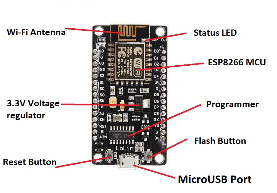
MicroUSB Port: This port is used for connecting the NodeMCU board to your laptop or desktop.
Reset Button: This button is used for resetting the NodeMCU board.
Flash Button: This button is used for flashing firmware onto the board.
Programmer IC: This IC is used by the board to upload code to the ESP8266 MCU.
3.3V Voltage Regulator: This voltage regulator is used to convert 5V from the MicroUSB cable to 3.3V as ESP8266 runs on 3.3V.
ESP8266 MCU: This is the main IC that will store code and perform all the tasks.
Wi-Fi Antenna: This is used for establishing communication with the other Wi-Fi devices.
Status LED: This LED will indicate power status and connection status.
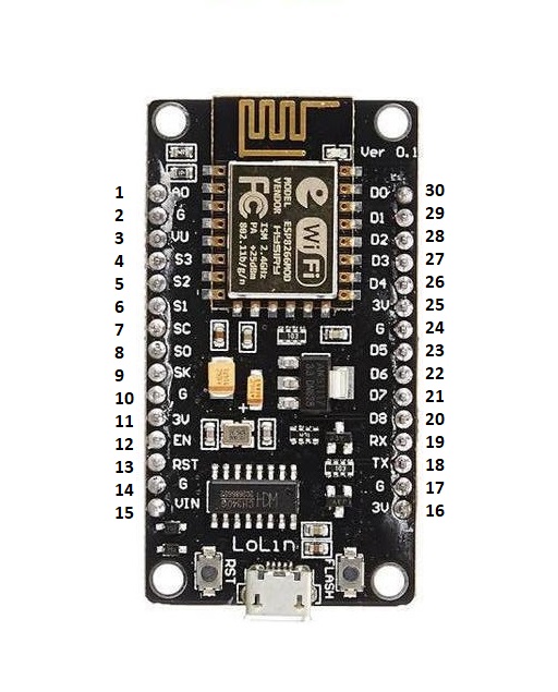
NodeMCU ESP-12E Pin Configuration
|
Pin No. |
GPIO Pins |
Board Pins |
Other Pin Use |
Arduino Pins |
|
1 |
A0 |
ADC |
||
|
2 |
RSV |
Reserved |
||
|
3 |
RSV |
Reserved |
||
|
4 |
GPIO10 |
SD3 |
||
|
5 |
GPIO9 |
SD2 |
||
|
6 |
GPIO8 |
SD1 |
MOSI |
|
|
7 |
GPIO11 |
CMD |
CS |
|
|
8 |
GPIO7 |
SD0 |
MISO |
|
|
9 |
GPIO6 |
CLK |
SCLK |
|
|
10 |
GND |
|||
|
11 |
3V3 |
|||
|
12 |
EN |
|||
|
13 |
RST |
|||
|
14 |
GND |
|||
|
15 |
VIN |
|||
|
16 |
GND |
|||
|
17 |
3V3 |
|||
|
18 |
GPIO1 |
TX/D10 |
TXD0 |
D1 |
|
19 |
GPIO3 |
RX/D9 |
RXD1 |
D3 |
|
20 |
GPIO15 |
D8 |
HCS/RTS0/PWM/TXD2 |
D15 |
|
21 |
GPIO13 |
D7 |
HMOSI/CTS0/RXD2 |
D13 |
|
22 |
GPIO12 |
D6 |
HMISO/PWM |
D12 |
|
23 |
GPIO14 |
D5 |
HSCLK?PWM |
D14 |
|
24 |
3V3 |
|||
|
25 |
GND |
|||
|
26 |
GPIO2 |
D4 |
TXD1 |
D2 |
|
27 |
GPIO0 |
D3 |
FLASH |
D0 |
|
28 |
GPIO4 |
D2 |
SDA/PWM |
D4 |
|
29 |
GPIO5 |
D1 |
SCL |
D5 |
|
30 |
GPIO16 |
D0 |
WAKE |
D16 |
Important note: While writing the Arduino code, we will be using the pin number as mentioned in the Arduino pins column.
Programming the NodeMCU board ESP-12E with Arduino IDE
Step1: Get ready with your NodeMCU Board.
Step2: Connect the NodeMCU board to the laptop or desktop.
Step3: Open the Arduino IDE
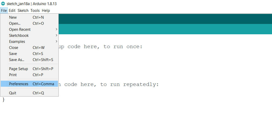
Step4: Click on the file option

Step5: Click on the Preferences
Step6: Paste this link in the additional board manager URLs: http://dan.drown.org/stm32duino/package_STM32duino_index.json
Click on the OK

Step7: Click on the tools

Step8: Click on the Board
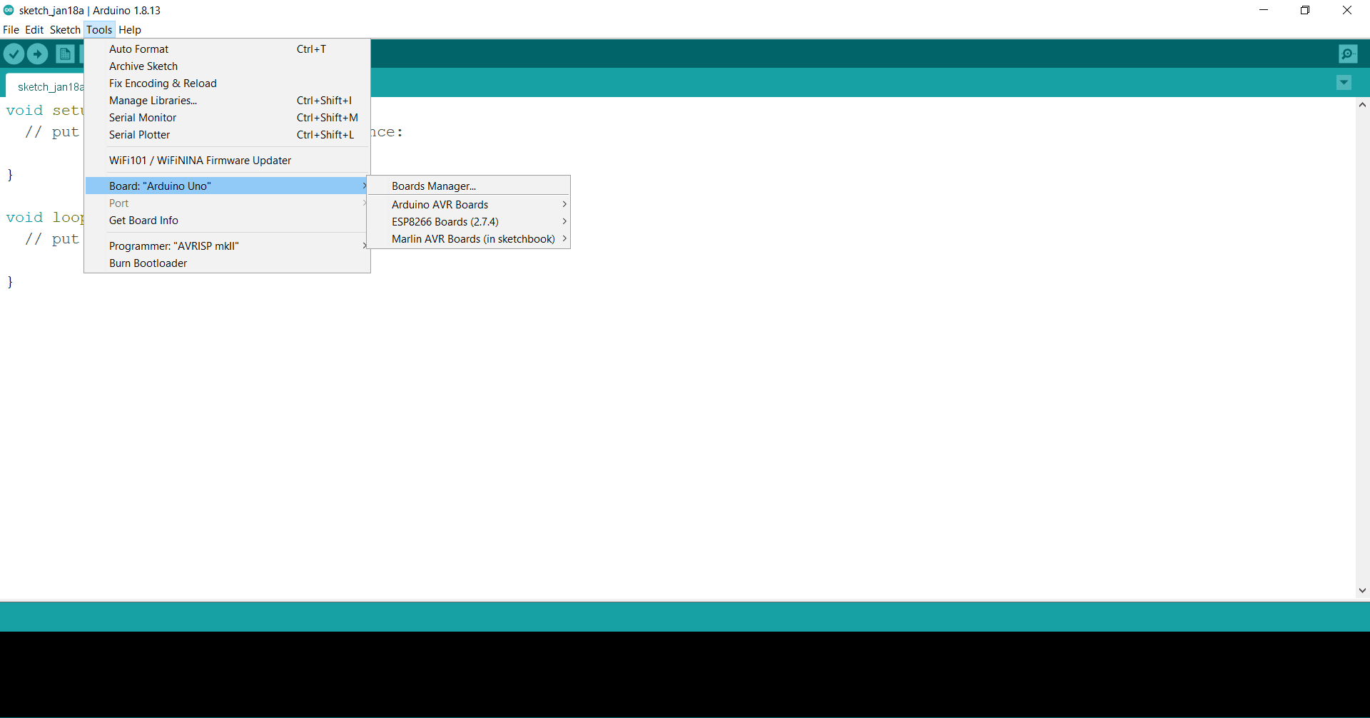
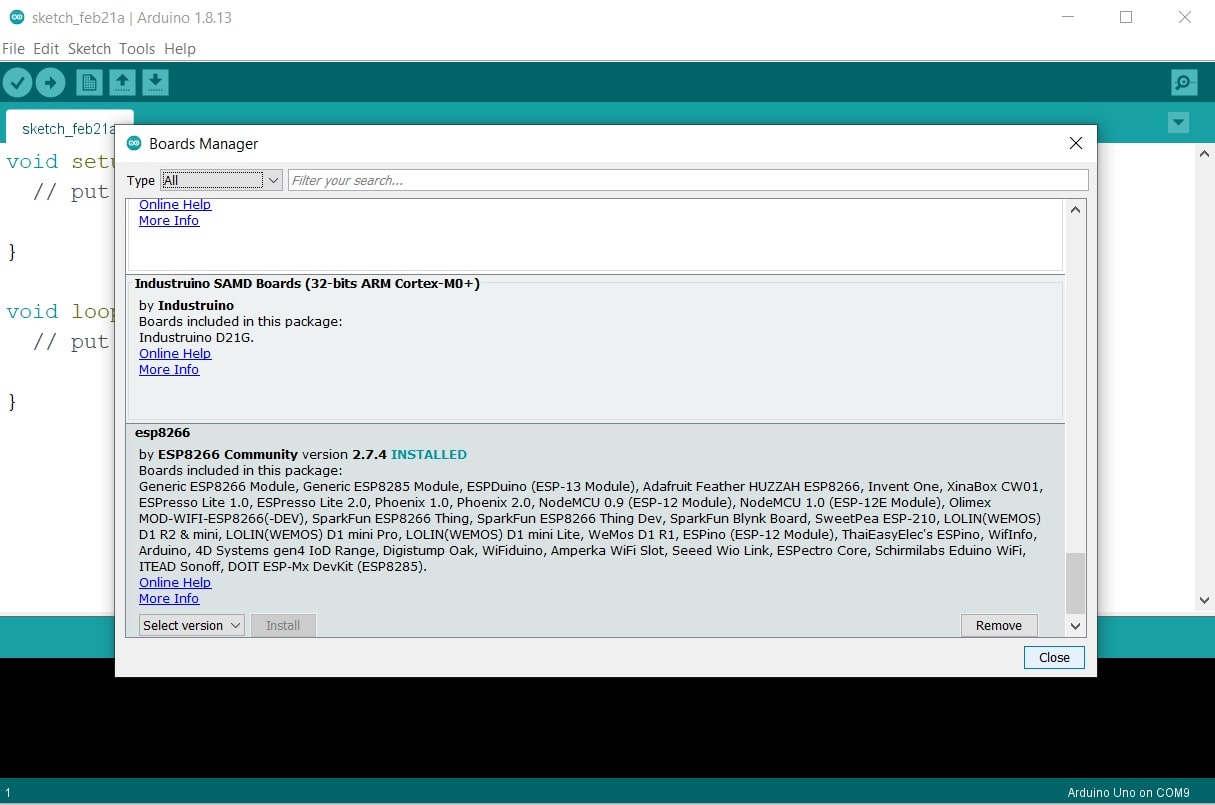
Step9: Click on the Board manager and wait for some time
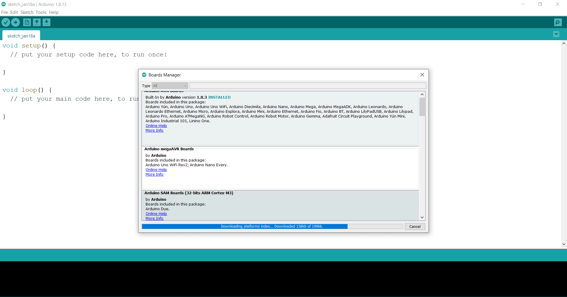
Step10: Scroll down and find the esp8266 and then click on install. Wait for some time till the board is downloaded.
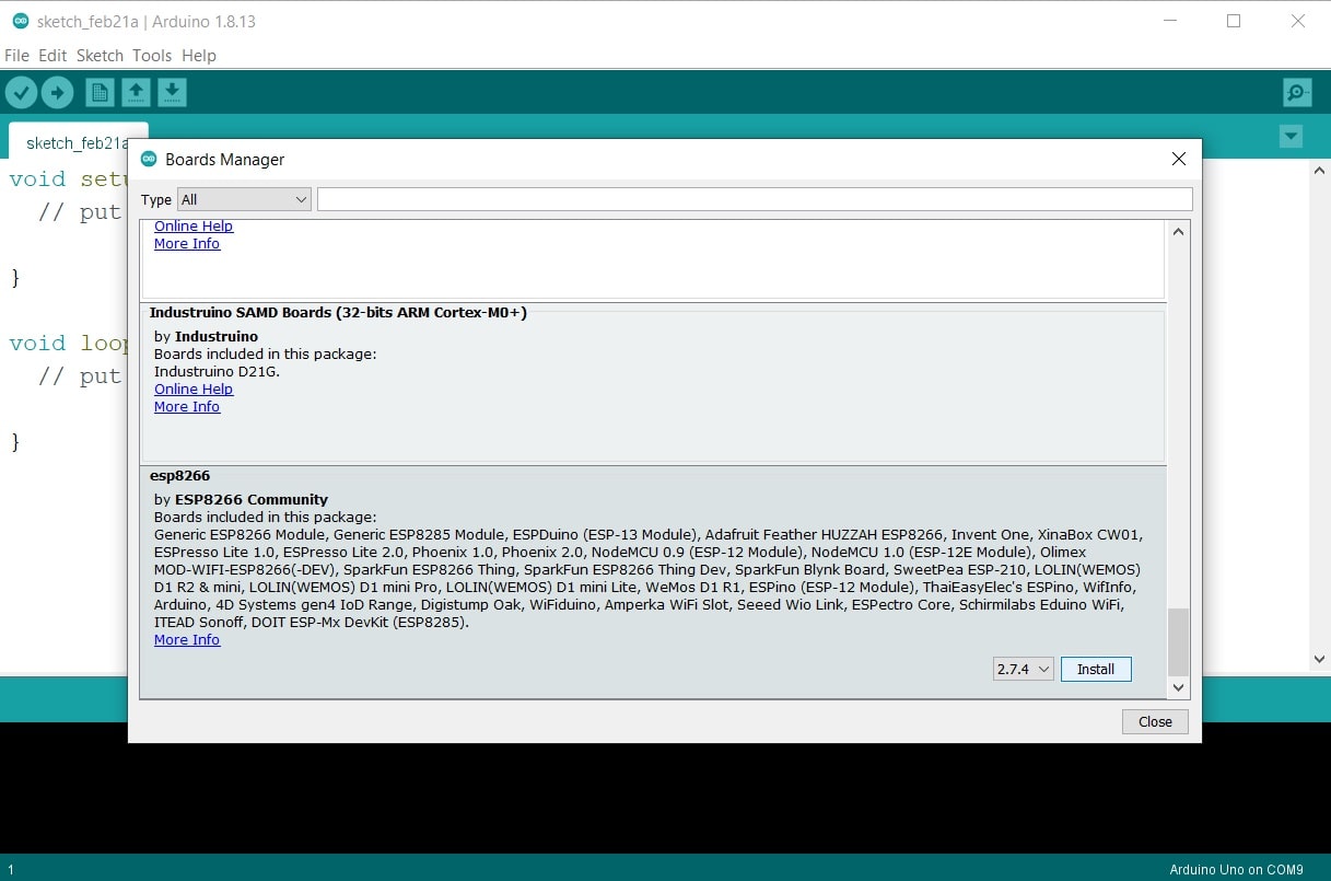
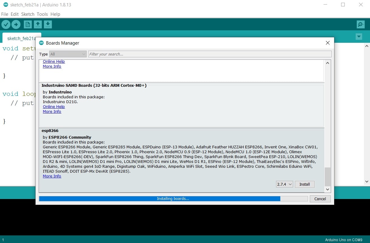
Step11: Close the board manager after installation
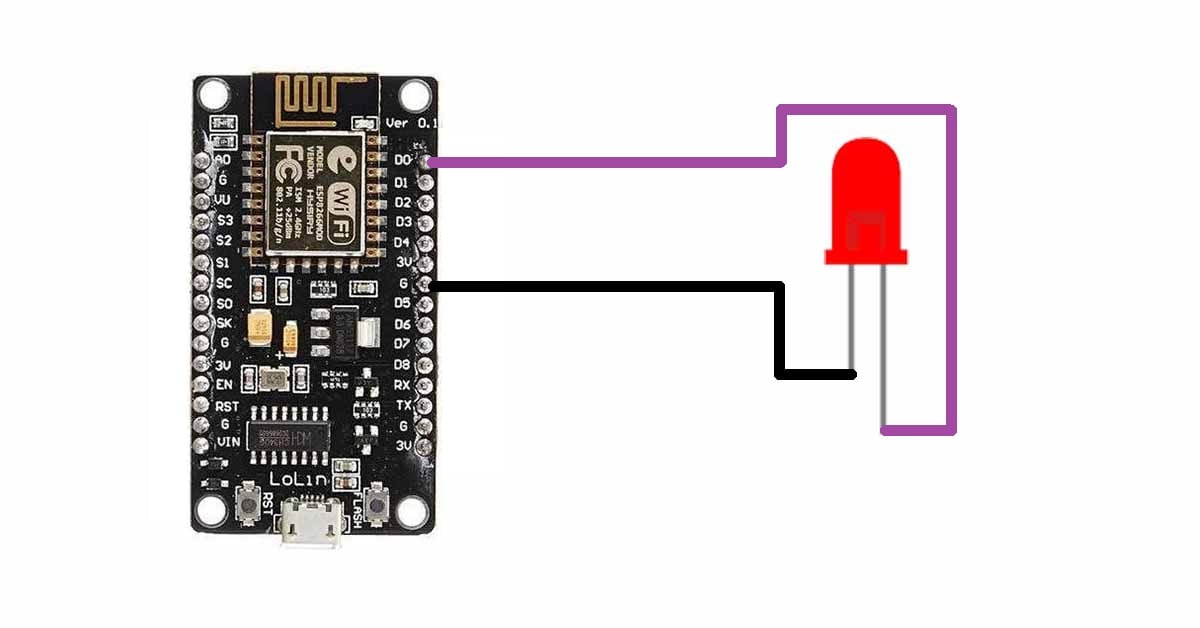
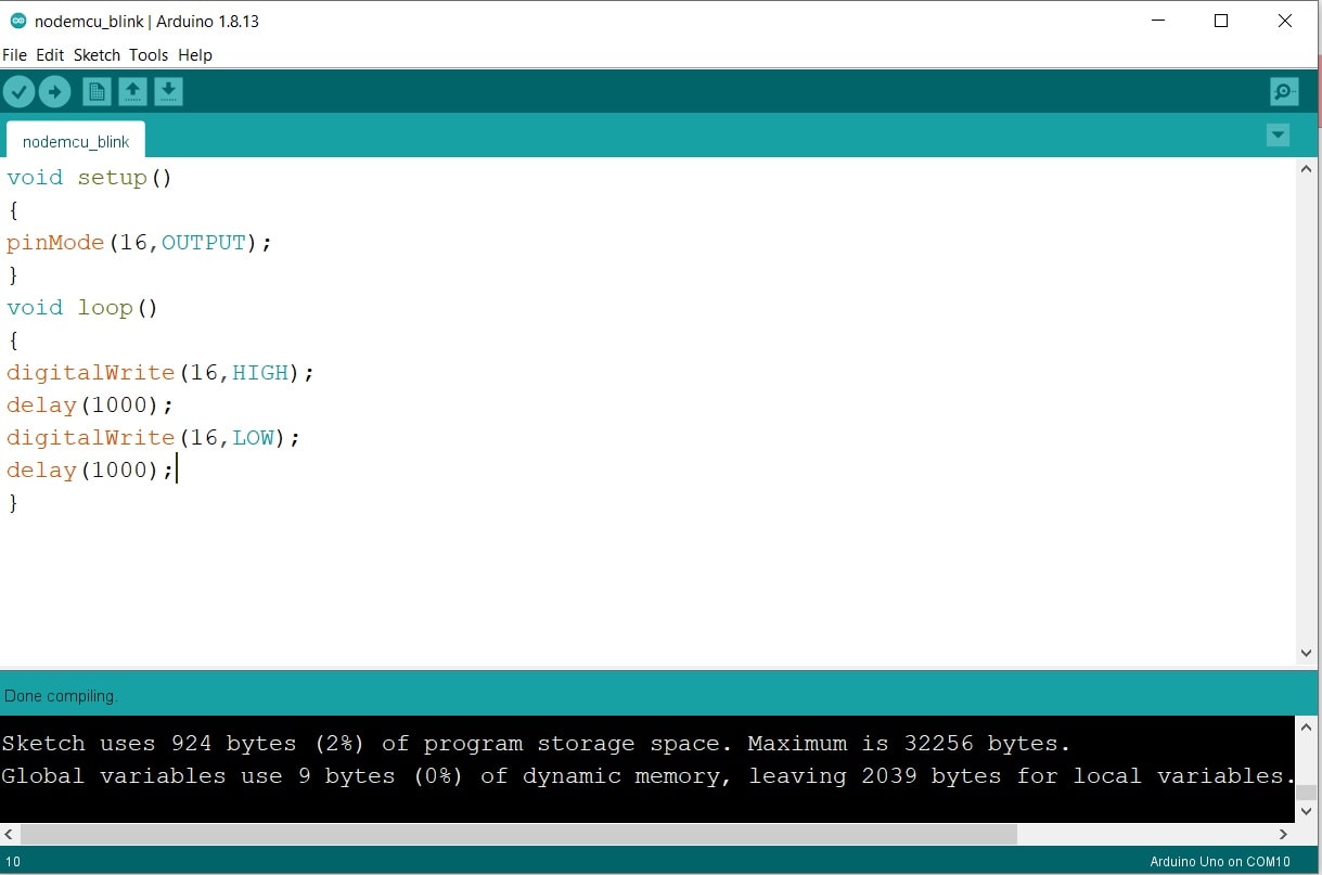
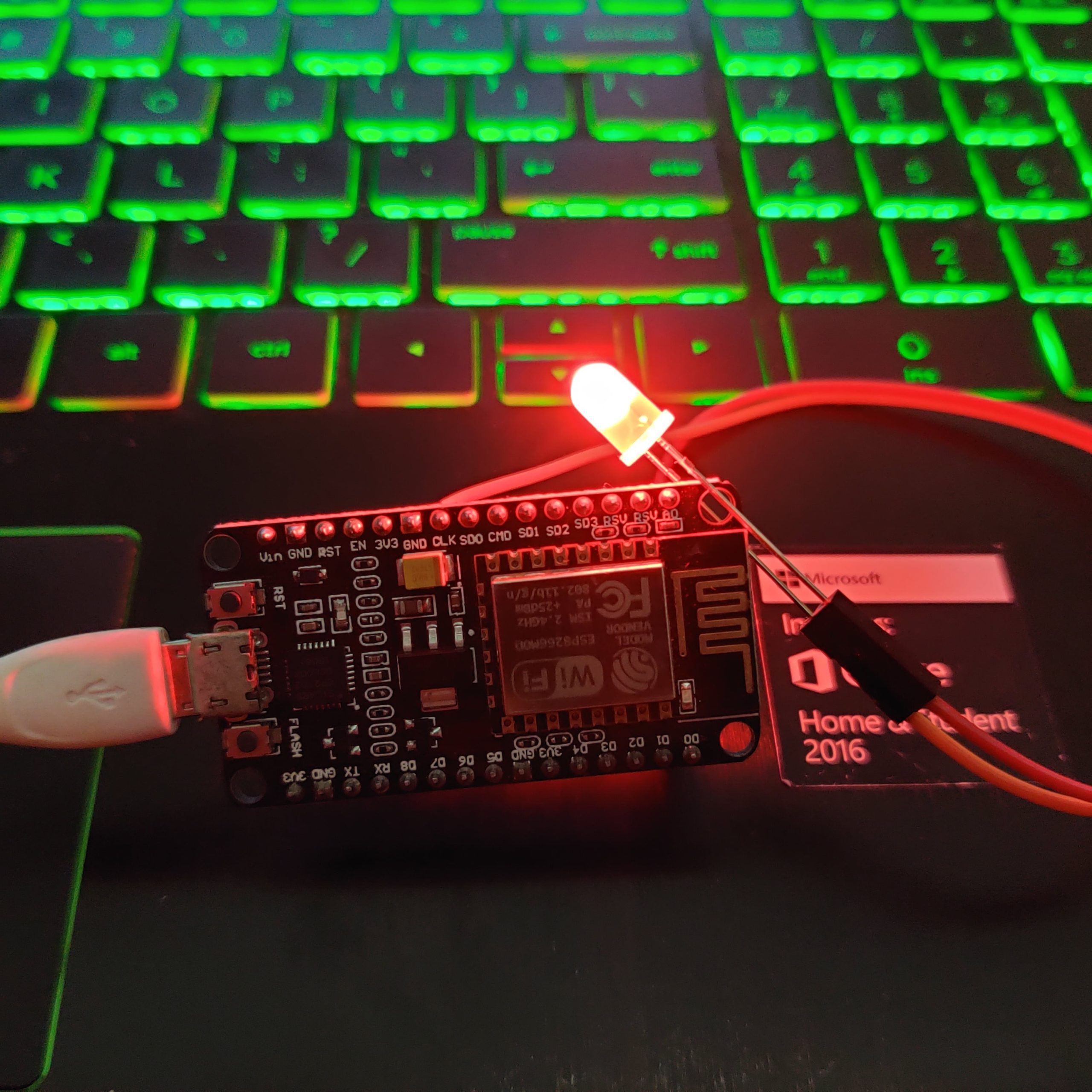
Now, we will upload our first LED blinking code to the board. Paste this code in Arduino IDE. Connect an LED to the D0 pin of the board as shown in the diagram. In terms of Arduino mapped pins, D0 pin of the NodeMCU board is a D16 pin in Arduino, you can refer to the pin configuration table for this. While writing your code for the NodeMCU, you just have to use the pin number as per the Arduino mapped pins. Rest all the commands are the same.
void setup()
{
pinMode(16,OUTPUT);
}
void loop()
{
digitalWrite(16,HIGH);
delay(1000);
digitalWrite(16,LOW);
delay(1000);
}
Circuit diagram for connecting an LED to the NodeMCU board
Step1: Open Arduino IDE and paste the code
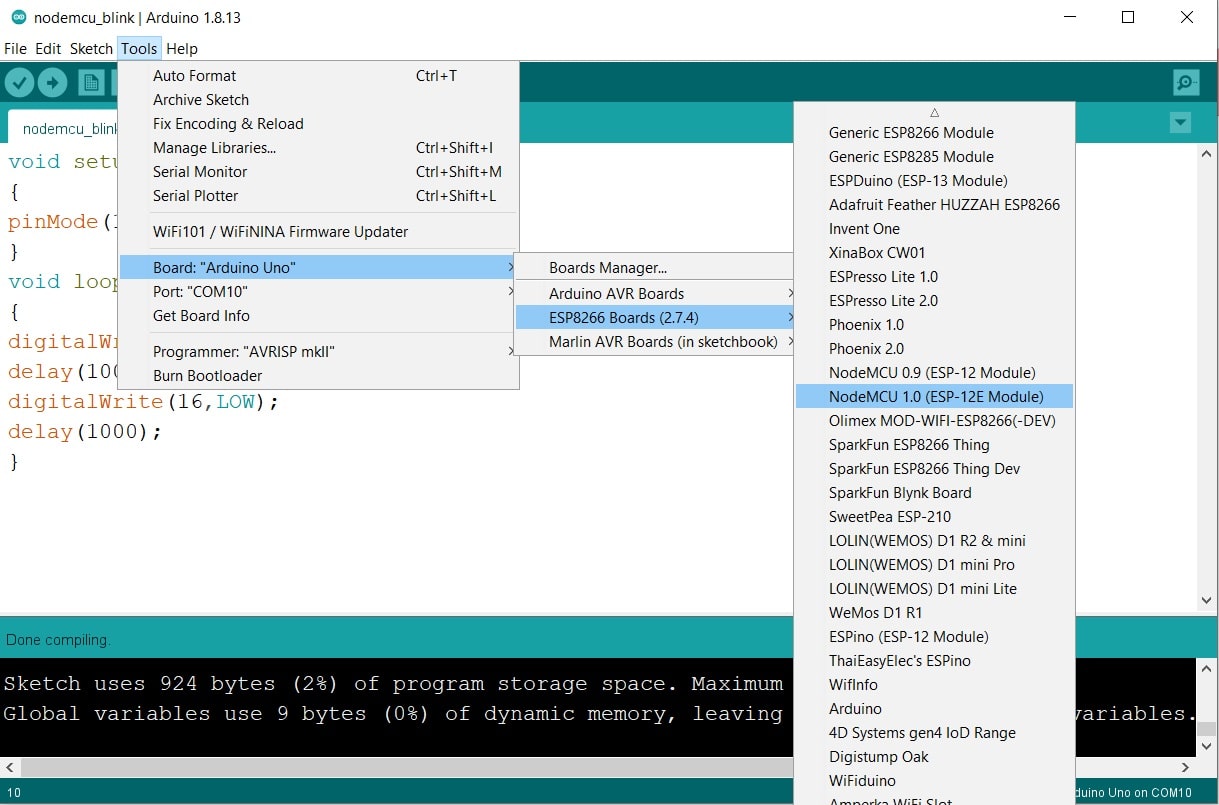
Step2: Click on the Tool tab and then click on boards.
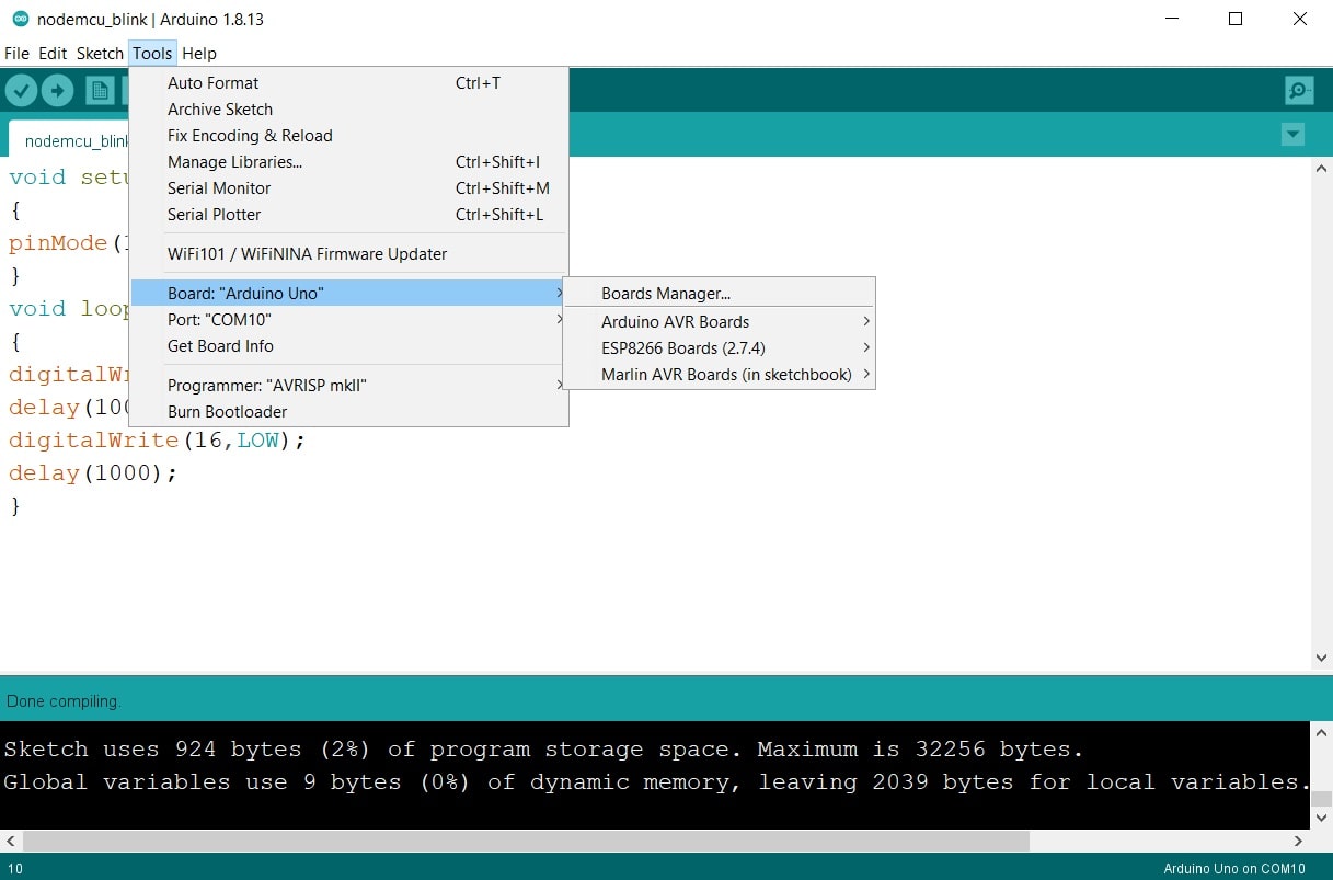
Step3: Select the ESP8266 Board option
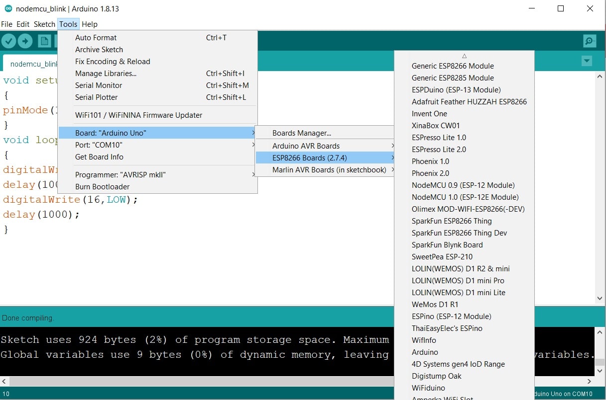
Step4: Select the NodeMCU 1.0
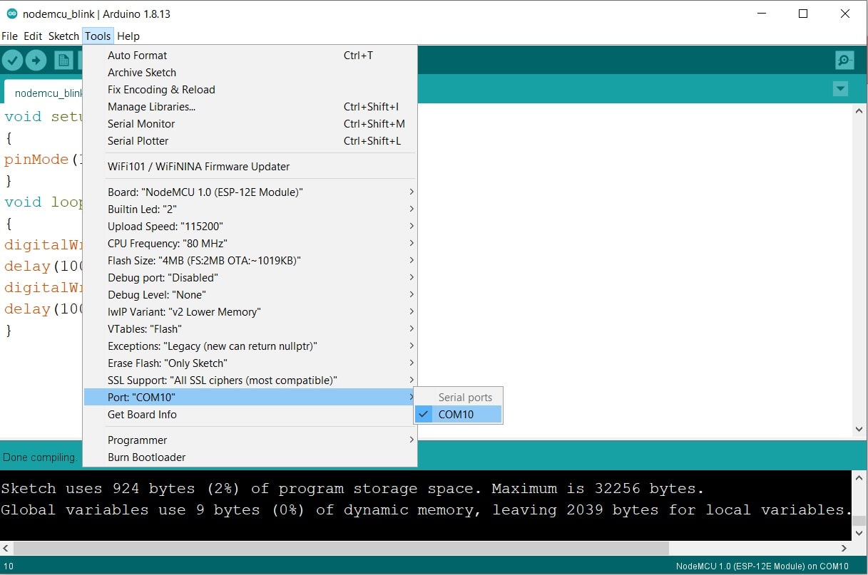
Step5: Select the Port. It my case it is COM10
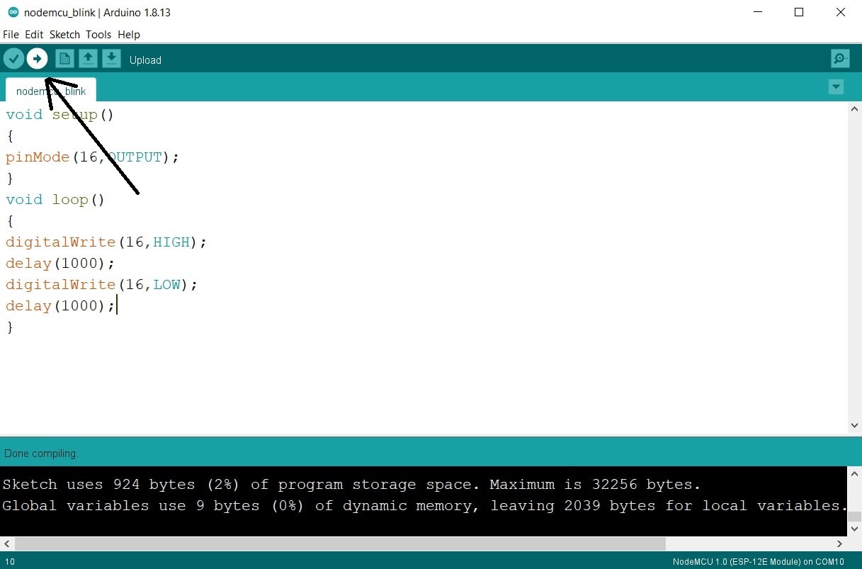
Step6: Click on upload button and your code will be uploaded
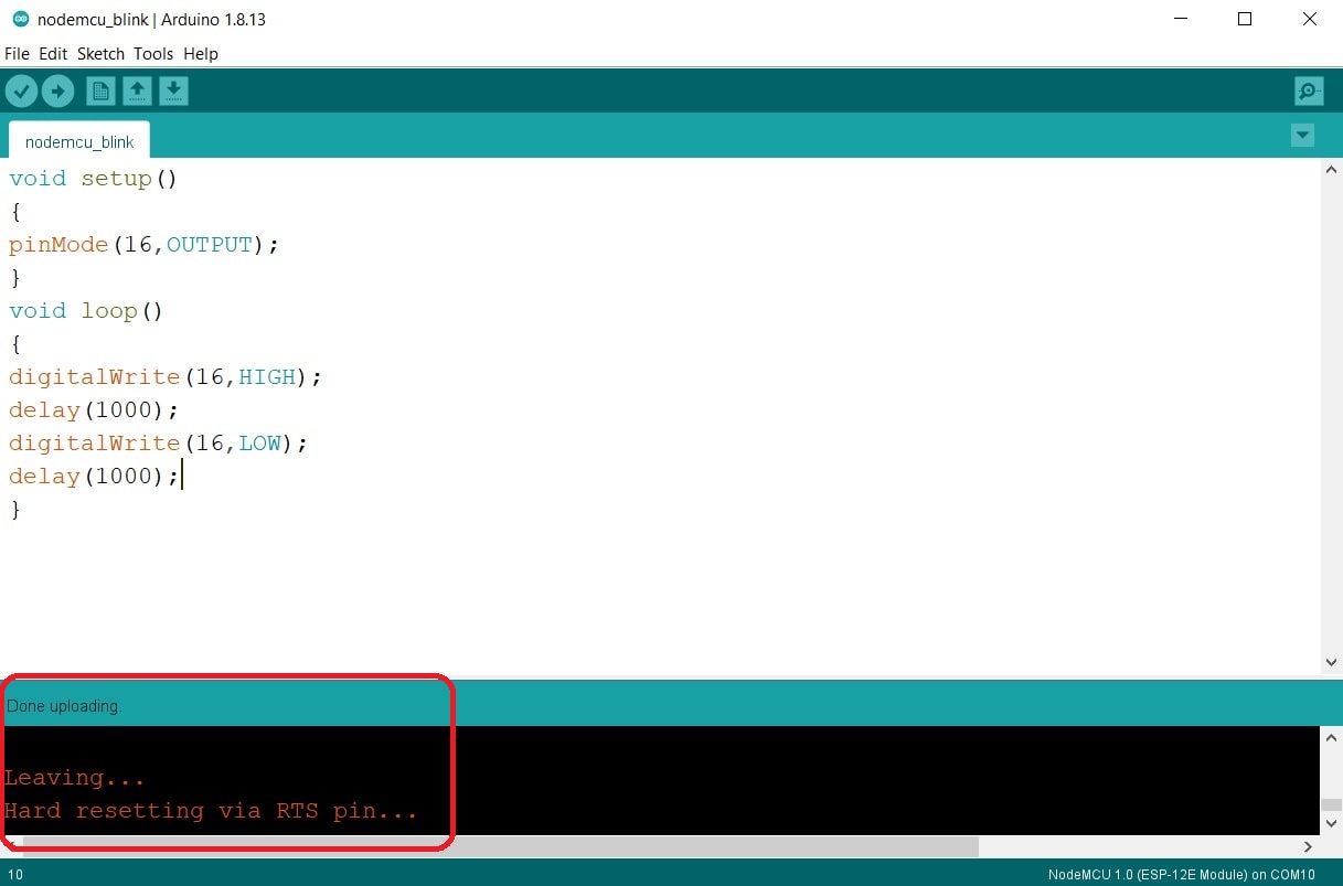
Output result
Comments are closed.