Description.
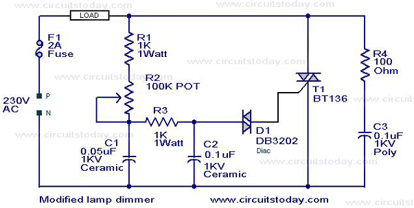
This is a modification of the circuit Simple Lamp Dimmer/Fan Regulator previously posted here. The working of the circuit is same as that of the previous, but in addition a snubber circuit consisting of resistor R4 and capacitor C3 is included to improve the performance of the triac T1. A fuse is also included for better safety. I think this is the better circuit to try .
Circuit diagram with Parts list .
Notes.
- No matter how what ever may be the load lamp,fan , heater or anything it should be rated less than 200 Watts.
- No matter how what ever may be the load lamp,fan , heater or anything it should be rated less than 200 Watts.
- Assemble the circuit on a good quality PCB or common board .
- Almost all parts of the circuit are live with potential shock hazard.Be careful.
17 Comments
Could you please give a calculation of the value of the component R dab C on the line?
Thank you
What correlation with the value of the load used?
Sorry, R and C
Thanks
Could you please give a calculation of the value of the component R dab C on the line?
What correlation with the value of the load used?
Thank you
Ok, you have tried but change it again
Thanks! but would you please explain more about R4 and C3 i wanna know that how them improve the TRIAC performance?
Thanks for the schematic, I tried this one and it worked just great, I tried adding 2 more diacs in series with the first one to be able to control the entire range 0% to 100% of the power on the output, does changing the pot’s value give the same result?
Shouldn’t the load be connected between R1 and T1 instead between R1 and F1?
This looks like a good circuit.
I need to use it for a 570W 2.6A 220-240Vac drill, as well as a 60W soldering iron for the same voltage. The frequency is 50Hz.
How can I increase the power handling capacity of this circuit t 1KW?
Why is there no choke? Is it because there is a snubber circuit?
Thanks
Max
If C3 is rated for 1kV it is not be the problem. raise R1 value to 100K and try. If 330K 1watt pot is available replace 100k with that. it will have more control range.
i have tried this circuit but the light is continuously glowing without any deduction in the intensity please give a suggestion to solve my problem.i have used 0.1uf ceramic capacitor instead of 0.1uf polyester on the snubber circuit.does this have any effect on my circuit.plz hlp me
THANK YOU
can i change the R1 POT 100k for other value? The circuit dimmer only to 50% light. Can i dimmer more?
Hi, I’ve just tried this circuit and I noticed that putting another Diac in series with the first one will increase the control range, 1Diac: 220 to 180 volts, 2Diacs: 220 to 80 volts, 3Diacs: 220 to 0 volts.
I used a 60 Watt lamp as a load, so I had the previous results, changing the pot’s range maybe another solution, but I’m telling the one I’ve tried.
Anyway, I’m planning to do an Arabic walk-through with the circuit I’ve made, make sure to visit my linked blog (just click my name).
wish you luck 🙂
give me the duty cycle range
please give a diagram
please publish LED’s bright condrolsirciut
What is the wattage suggested for R4?
Hello,
Could you please give a method of calculating the values of components such a R1, because i have a welding transformer with dimmer placed into the primary, and this R1 was burn and i can not know the most correct value, i have also tested many Resistance in serial with pot 47K even i changed with 100K but it doesn’t work, could you please help me.
Best Regards
Hicham