Description.
Here is a simple mains power failure alarm/detector circuit that produces an alarm whenever the mains supply fails. Lot of such circuits are available, but the peculiarity of this circuit is that it requires no back up power source like a battery to power the alarm when the mains is absent.
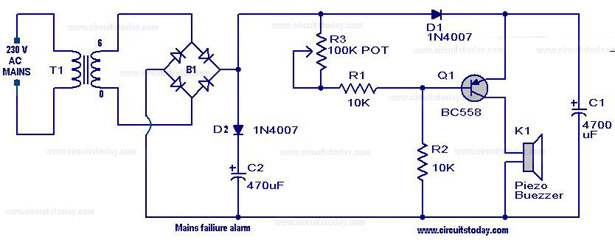
When there is mains supply the transistor Q1(BC558) will be OFF and the capacitor C1 will be charged. When the mains supply fails the transistor Q1 becomes ON and the capacitor C1 discharges through the Q1 to drive the buzzer to produce an alarm. The capacitor C2 is the filter capacitor for the bridge. Diode D2 prevents the discharge of the C2 when mains fails. If D2 is not there, the alarms will remain silent for a time capacitor C2 to fully discharge after the power failure.
Circuit diagram with Parts list.
Notes.
- T1 can be a 230V primary 6V secondary 500mA transformer.
- B1 can be a 1A bridge.You can make the same using four 1N 4007 diodes.
- All capacitors are rated 25V.
- You can use any general purpose PNP transistor (like BC158,BC177 etc) as Q1.
26 Comments
this circuit is wrong . it will always keep the buzzer on
This circuit is wrong. I have edited this circuit and tested it is working fine. The buzzer will remain OFF if power is present. As soon as the power is down the buzzer will be switched ON till the capacitor is charged. No use of D2 and C2 here. Use a diode instead of series combination of (100 K pot and 10 K). connect the anode of diode to VCC and cathode to Base of PNP transistor. Use this circuit i have uploaded and edited
https://www.facebook.com/photo.php?fbid=10151982284009625&set=o.177778408912651&type=1&ref=notif¬if_t=comment_mention&theater
Sir,
plzzzz help me..
I want to know the applications of ‘main supply fault detector alarm circuit.’
.
Plzz respond for message soon
Sir,
i want to know the applications of ‘main supply fault detector alarm circuit’
sir plzzzzz give me reply as soon as possible
i have tried circuit but buzzer keeps on giving sound even when there is power supply
this circuit gives an alarm even when power supply is on…capacitor of 470 micro farad is of waste..100k pot is not placed in correct position..don’t try this circuit.it is just waste of time
Got to agree with this. Replaced 470uF with 18000 uF gives about 2 mins of alarm. Unable to sort out the biasing so the alarm on all the time. Finally gave up with this, replaced it all with a small relay using the N/O contacts to sound the bleeper.Still fun waste of an hour.
Sri should be N/C contacts as relay is energised when the power is on so bleeper sounds when power fails.
reply soon plz
what is the need of bridge rectifier
sir,we are yet to start this project can you explain the working of the transformer,and why do we need 100K pot what is the necessary ?
can you please explain the working of each part.and wat is the use of it
Dear sir,i really appreciate your open sourcing mind..and i need a little help..i need a circuit which only produces a alarm for shorter delay say 20s when connected to mains..
D rlay of hig&low cutoff only enrgis aftr 10s whn swtchd ON.whn vR1&VR2 is varied fails 2enrgis&dlay.hlp
A simple diagram for 3 phase AC mains failure (audio with LED)alarm circuit.Inverter is also available i.e.Power for the said circuit can be from Inv. O/P.When the mains come and go, the alarm should work.Can you help?
i have constructed the circuit but its not properly working the buzzer beeps when the power supply is provided but it doesnt beeps on failure please solve the problem
can i use led istead of buzzer
I have made this circuit but the buzzer keeps beeping while connected to the main supply. Can some help me on this??
Adjust the POT R3
What is The Purpose of D2 and C2.I feei nothing.