Smart LCD with Automatic Brightness Adjusting Using Arduino and LDR Sensor
Here is a simple Arduino project that focuses on adjusting the brightness of an LCD screen whenever there isn’t sufficient light in a room. The Arduino reads the surrounding light intensity using an LDR sensor. The room temperature and humidity range will also be displayed on the LCD. The entire hardware of this simple project using Arduino can be divided into three parts. The sensors, Arduino board, and the LCD module.
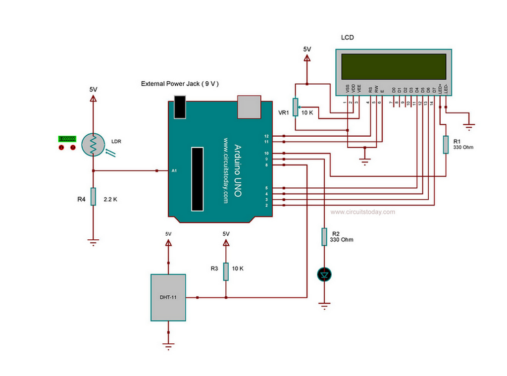
Circuit Diagram – Smart Brightness Control
Let’s have a look at the sensors first.
Sensors – LDR and DHT11
In order to detect the intensity of light, we use a sensor called an LDR (Light Dependent Resistor). The LDR is a special type of resistor which allows higher voltages to pass through it (low resistance) whenever there is a high intensity of light, and passes a low voltage (high resistance) whenever it is dark. The resistance of an LDR is inversely proportional to the intensity of the light falling on it. So when there is sufficient amount of light in the room, the resistance of the LDR will be low. So the voltage dropped across the LDR will be low and vice versa. The voltages dropped across the LDR is given as input to the analog input pin A4 of the arduino board.
Temperature and humidity ranges are obtained using a DHT-11 module. The DHT11 is a basic, ultra low-cost digital temperature and humidity sensor. It uses a capacitive humidity sensor and a thermistor to measure the surrounding air and spits out a digital signal on the data pin (no analog input pins needed). Its fairly simple to use, but requires careful timing to grab data. Arduino provides a library which makes easier for fetching data from the DHT11 module.
Arduino UNO Board
Arduino UNO is a microcontroller board, contains an on-board power supply, USB port to communicate with PC, and an Atmel microcontroller chip. It simplifies the process of creating any control system by providing the standard board that can be programmed and connected to the system without the need of any sophisticated PCB design and implementation. ThArduinono board has to be programmed to read the sensor values and displaying it accurately with proper LCD brightness. This is done by reading the LDR sensor connected to analog input A4 of the arduino and the DHT11 module connected to the 6th digital pin of arduino. The voltage range that can be applied to a particular analog input of the arduino is 0 to 5V. This range can be converted into a digital value between 0 and 1023 using analogRead () command.
LCD Module
Interfacing LCD module to arduino is another important step in this project. JHD162A is the LCDmodule used here. JHD162A is a 16×2 LCD module based on the HD44780 driver from Hitachi. The JHD162A has 16 pins and can be operated in 4-bit mode or 8-bit mode. Here we are using the LCD module in 4-bit mode. In 8 bit mode we require 8 data pins and 3 control pins whereas in 4 bit mode, data is sent using 4 data pins and 3 control pins. In our project, R/W pin is always grounded so we require only 6 pins in 4 bit mode, thus saving no of pins. During interfacing the library is first initialized and then define pins using the command LiquidCrystal lcd(RS, E, D4, D5, D6, D7), pins are assigned in this order.
In the program we can see this command as LiquidCrystal lcd(12, 11, 5, 4, 3, 2), here RS pin to 12, Enable pin to 11, D4 pin to 5, D5 pin to 4, D6 pin to 3 and D7 pin to 2 respectively. The led + pin of the LCD module is connected to one of the pwm pin( 10th pin) of arduino through a 330 ohm resistor. The brightness of the LCD module can be varied by writing pwm vales on this pin.
The Program/Code
#include <dht.h>
#include <LiquidCrystal.h>
#define DHT11_PIN 8
LiquidCrystal lcd(12, 11, 5, 4, 3, 2);
dht DHT;

int LDR_pin=A1;
int back_light=10;
int led=9;
int LDR_out;
int pwm_back_light;
int pwm_led;
int humidity;
int temperature;


void setup()
{
 pinMode(LDR_pin,INPUT);
 pinMode(back_light,OUTPUT);
 pinMode(led,OUTPUT);
 lcd.begin(16,2);
 Serial.begin(9600);
}

void loop()
{
// READ DATA
 int chk = DHT.read11(DHT11_PIN);

 // DISPLAY DATA TO LCD
 humidity=(DHT.humidity);
 temperature=(DHT.temperature);
 lcd.setCursor(0,0);
 lcd.print("Humidity=");
 lcd.print(humidity);
 lcd.print("%");
 lcd.setCursor(0,1);
 lcd.print("Temperature=");
 lcd.print(temperature);
 lcd.print((char)223);
 lcd.print("C");

LDR_out=analogRead(LDR_pin);
 pwm_led=LDR_out/4;
 pwm_back_light=255-(LDR_out/4);

 Serial.println(pwm_back_light);
 analogWrite(back_light,pwm_back_light);
 analogWrite(led,pwm_led);
 delay(1000);
}
First of all we have configured the A4 pin of the arduino uno as input pin to read the the LDR sensor output. In the setup function, the “Serial.begin(9600)” command will help in communication between the Arduino and serial monitor.
In the loop function, we will read from the sensor analog pin A4 and will store the values in the “ldr_out” variable. Then we will map these values to 0-255 range. The mapped values is then used to generate pwm (pulese width modulation) output at the 10th pin of arduino (which is connected to the led+ pin of LCD module). In this way the brightness of the LCD can be varied with surrounding light intensity.
A library is used in the program for obtaining readings from DHT11 module. The temperature and humidity readings are obtained from functions “DHT.temperature” & “DHT.humidity” respectively.
Demonstration Video
We finished our tutorial on how to make a Smart LCD that adjusts brightness automatically sensing ambient light. Try this project yourself and see how it goes.
Comments are closed.