- Password Based Keypad Door Lock
In this article, a digitally secured lock based on password verification is explained. The system uses a seven segment display array to show the password, a matrix keypad to enter the numbers/password and operates a relay (to activate the solenoid valve) for locking and unlocking purpose. The system alarms through a buzzer if a wrong password is entered for 3 times continuously and an SMS is sent to a predefined contact number. The password can be changed whenever required, but only after correctly entering the present password. The password is stored in the EEPROM of the microcontroller so that, power failure or reset of the system does not affect the password recognition.
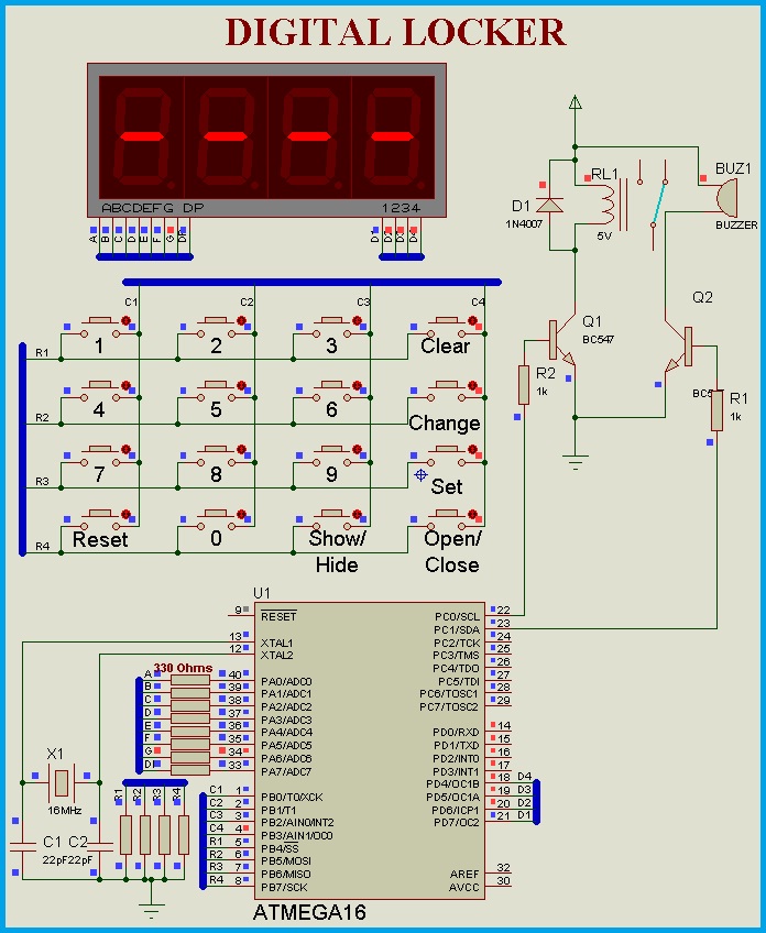
Circuit Diagram
The system contains a seven segment display array, a 4X4 matrix keypad and a GSM module to send the status message. Based on these requirements, any microcontroller with 3 I/O ports and one UART peripheral is sufficient. In this article ATMEGA16 microcontroller is used. The circuit is developed using the Proteus Simulation software to demonstrate the operation. There is a real-time feature called the ‘Virtual Terminal’ in this software which is used in this article to send the SMS through a GSM Module connected to the computer.
The circuit diagram for connecting the GSM module to the computer is shown below. A detailed explanation on this procedure is provided in the article, “Virtual Comports in Proteus”.

The Matrix Keypad
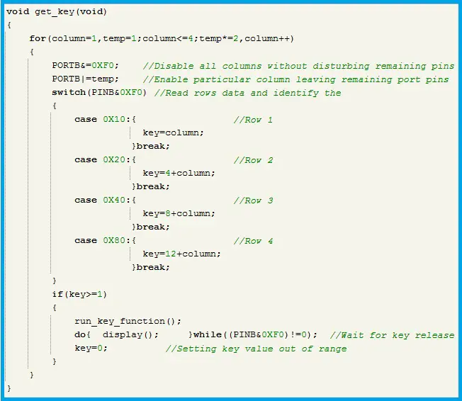
In this circuit, a 4X4 matrix keypad is used to enter the password and to interact with the system. A function called the ‘get_key’ function is used to read the pressed key and this key information is passed to the ‘run_key_function’ which is a ‘switch statement’ with 16 cases, and is assigned with one case for each key. As there are 16 keys in the keypad, key value ranges from 1 to 16 and by default, the key value is set out of this range during initialization of the key variable. The ‘get_key’ function refreshes the columns and reads the rows for detecting the pressed key (if any). Whenever a key is pressed this default value is replaced by the currently pressed key. Now, the ‘run_key_function’ is executed and corresponding statements for the pressed key are executed. After execution of these statements, the display function is called until the pressed key is not released. Soon after the key is released, again the key value is set out of range. Below is the program code for the functions ‘get_key’. The ‘get_key’ function can be easily modified for keypads other than the 4X4 matrix.
The Display
As the password is of four digits, four seven segment LED’s are multiplexed. There is an option to show/hide the password while entering. The display function presented in this article uses one for loop and it can be modified easily if the number of digits is varied. If the show option=1 then digits are shown as they are and if show option=0 then the ‘G’ segment of the displays is enabled instead of the entire digit. The program code for the display function is shown below.
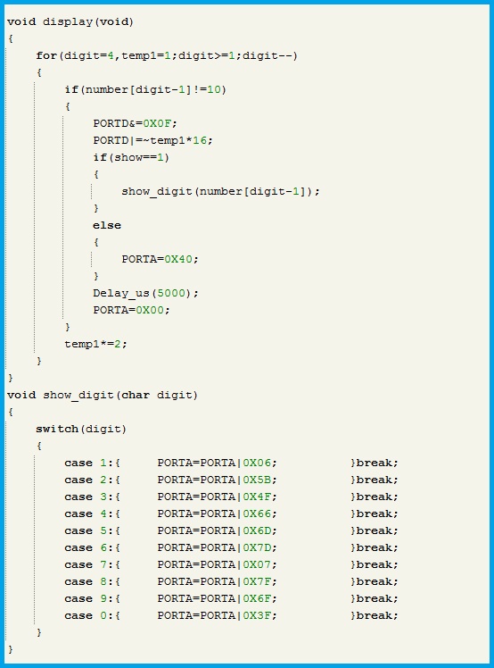
The entered number is read and stored in the form of an array so, each digit of the number is sent to the display array after enabling the corresponding digit. Here, the show/hide option is read and data is sent depending on the value of the ‘show’ variable as discussed above.
The ‘clear’ key is used as the backspace to clear the last entered key. When this clear key is pressed the array index is decremented by one and the corresponding array data is cleared and set to any default value other than 0 to 9, so that the history of the entered numbers will be deleted. Here we used 10 as the default value. The program code for this backspace operation is found under case 4 (key=4) of the ‘run_key_function’.
After entering the 4-digit password, the user has to press the ‘open’ key to unlock the locker. Now, the verification function is executed and the result is stored in the ‘match’ variable. If match=1 then the locker will be unlocked by activating the relay. If match=0 then the ‘miss_match’ count is incremented by one and buzzer is activated for one second and the number is cleared. If this count reaches to three times then, the alarm/buzzer is activated for 10 seconds and an SMS is sent to the mobile phone number fed in the program. The program code for the opening or blocking of the system is found in case 16 (key=16) of the ‘run_key_function’.
Reading and Verifying the Entered Password
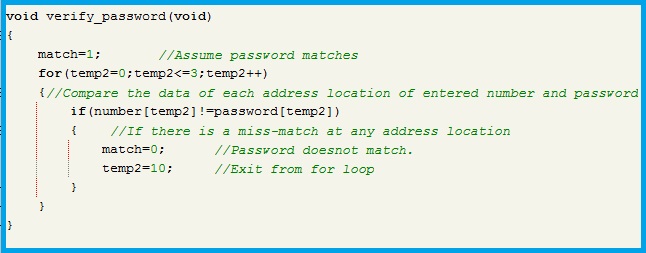
The entered number is read and stored in the form of an array for easy processing. When a key corresponding to numbers 0 to 9 is pressed, the number is stored in the current address location of the array and the address pointer is incremented through a variable ‘index’. So, when the next key is pressed, the number will be stored in the address location next to the previously entered digit. The array size is limited to 4 and entering beyond this limit leads to a run-time error. So, before storing the entered digit the value of index should be verified whether it is less than or equal to three and this is optional. The entered password is verified using the ‘verify_password’ function shown below.
Blocking the system
After three continuous wrong attempts the system will be blocked for one hour (time can be modified) and then the system resumes. When the system is blocked, if there is a power failure or if the unauthorized user tries to reset the system then the block state will be lost i.e.., the system operates normally. To avoid this, the information related to blocking and the time passed after blocking the system should be stored in the EEPROM. After every reset or the normal switch ON of the system, this information is read and if the system is previously under a blocked state then, this blocking continues for its remaining time and then the system resumes. The EEPROM related operations are performed in the Interrupt sub-routine of compare match interrupt of the 16-Bit timer. Below is the program code.
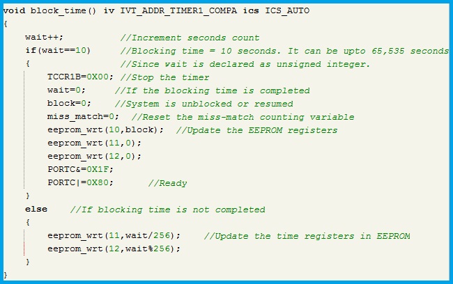
To block an unauthorized user, a 16-Bit timer/Counter is used. After blocking, an SMS is sent and the timer is initialized with a frequency of 16MHz/1024. The compare match registers of the microcontroller are preset to a count value equivalent to one second. So, a compare match interrupt is generated for every second. The waiting time is incremented for every second in the Interrupt sub-routine and the updated value is stored in the EEPORM. Thus, even if there is a power failure or reset condition, the time passed after blocking is available in the EEPROM registers and after reset of the microcontroller these values are read and blocking operation is resumed.
Changing the Password
The password can be changed only after entering the current password. When the system is successfully unlocked with the current password, the change key is activated. Now if the change key is pressed, the number array which contains the entered password will get updated to default values (i.e., = 10). But, the EEPROM registers still contain the password. Now enter the new password and press the set key. This will update the EEPROM registers with the newly entered password. From now on, this new password is used for verification. After Power ON or Reset of the system, this password is read from the EEPROM registers and stored in the RAM of the microcontroller. Below is the simulation output showing the update process of the EEPROM registers during a password change.
Simulation output of Changing the password
Sending an SMS
As mentioned earlier, the system will send an SMS after three wrong attempts. The SMS is sent through the GSM module connected to the microcontroller. In the circuit diagram, a COMPORT is directly connected to the microcontroller. But in real-time, the TTL Level TX and RX pins of the GSM module are connected to the microcontroller. The communication parameters are Baud rate=9600, Stop bits=1, Parity= None and Data bits=8.
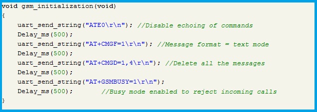
Before using the SMS commands certain parameters should be set after powering the GSM Module. These commands are grouped into the ‘gsm_initialization’ function. Before this, the module has to get ready, which may take around 15 seconds (safe boundary). Thinking logically, the SMS has to be sent after three wrong attempts. So, if we disabled the system for 3 seconds after every wrong attempt, the module will initialize properly even if we operate immediately after the Power On. The function is shown below and should be called at the time of sending the SMS.
The message is sent through the ‘send_sms’ function. Through a series of commands, the contact number and the message are sent to the GSM module and the module sends the message. The program for sending an SMS is shown below.

The simulation output is shown below. An SMS is sent after 3 wrong attempts. The blocking time sent in the message is one hour which can be varied during programming. The real-time mobile screen is included in the video file which shows the received message. In the below simulation the blocking time is set to 10 seconds.
Note:
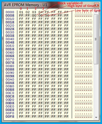
While implementing this circuit in hardware, please remember to write the EEPROM registers with a known password, the block variable and the time value locations to zero. Otherwise, the system cannot be opened. The programming software (burning/dumping software) will have a feature to write EEPORM data. Using this feature write the password and block status registers in the EEPROM at desired locations. In the below image the address locations 0 to 3 contain the password ‘1234’ and the location 10 contains block variable data=0 and 11, 12 address locations contains time value=0.
Download Program File
You can download the program file here – Keypad Door Lock Program using Atmega16
2 Comments
nice work, congratulations.