Interfacing RFID to 8051 .
RFID or Radio Frequency Identification is a method in which electromagnetic waves are used for transmitting data for the purpose of identifying tags attached to objects. An RFID system consists of a transmitter (tag) and a reader.The tag is encrypted with a unique code and the reader scans this code for the identification purpose. The tags are generally of two types: active and passive. Active tags have a battery fitted to it and it transmits the unique code periodically or in the proximity of the reader. Passive tags are powered using the electromagnetic induction from the signal transmitted by the reader. Typical applications of RFID are access control systems, ID cards, human identification, animal identification, payment systems, tagging books, replacing bar codes, tagging merchandise in stores etc . RFID tags are available in different shapes but the most common shape is in the form of a card. The RFID readers are available in the market in the form of a module with all the supporting hardware. This article is about interfacing RFID to 8051 microcontroller. The images of a typical RFID card and reader are shown below.
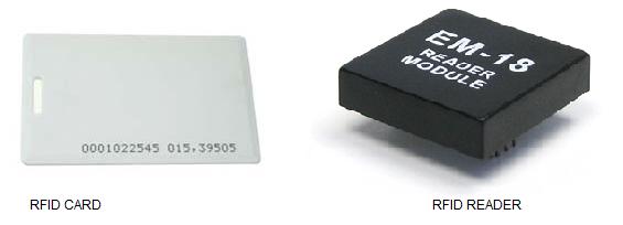
The RFID card is available in different sizes and shapes and the most commonly used type is shown above. The image of a typical RFID reader module is also shown above. Basically it contains a semiconductor memory for storing the unique ID code, modulating circuit and a coil. The coil acts as the power source by means of electromagnetic induction while in the vicinity of the reader and it also serves as the antenna for propagating the ID code. The modulating circuit modulates the unique code into the transmitted wave. The reader basically contains a coil and an electronic circuit. The coil serves as exciter for the card and also the antenna for receiving the signal propagated by the card. The electronic circuit demodulates this signal and converts it into a form suitable for the next stage (microcontroller). Circuit diagram for interfacing RFID module to 8051 microcontroller is shown below.
Interfacing RFID to 8051 circuit diagram.
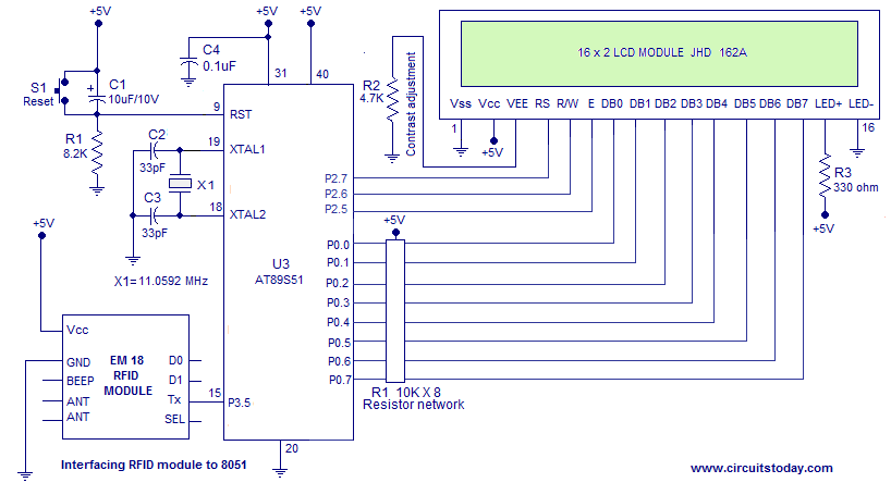
The full circuit diagram for interfacing RFID module to 8051 is shown above. The unique ID code in the RFID card is read by the circuit and displayed on the 16×2 LCD display. Tx pin of the RFID module is connected to Port 3.5 of the microcontroller. The microcontroller receives data from the RFID module through this channel. Switch S1, capacitor C1 and resistor R1 forms the reset circuit. Capacitor C2, C3 and crystal X1 are associated with the reset circuit.
Program.
RS EQU P2.7                  //equates P2.7 to RS
RW EQU P2.6                  //equates P2.6 to RW
E  EQU P2.5                  //equates P2.5 to E
ORG 000H                     //origin
MOV TMOD,#00100001B          //Timer1=Mode2 timer & Timer0=Mode1 timer
MOV TH1,#253D                //loads TH1 with 253D(9600 baud)
MOV SCON,#50H                //sets serial port to Mode1 and receiver enabled
SETB TR1                     //starts Timer1

MAIN:ACALL DINT              //calls DINT subroutine
     ACALL TEXT1             //calls TEXT1 subroutine
     ACALL LINE2             //calls LINE2 subroutine
     ACALL TEXT2             //calls TEXT2 subroutine
     ACALL READ              / /calls READ subroutine
     CLR REN                 //disables serial data receive
     ACALL LINE2             //calls LINE2 subroutine
     ACALL WRITE             //calls WRITE subroutine
     ACALL DELAY1            //calls DELAY1 subroutine
     SETB REN                //enables serial data receive
     SJMP MAIN               //jumps back to MAIN label

DELAY1:MOV R3,#46D           //loads R3 with 46D
BACK:  MOV TH0,#00000000B    //loads TH0 with all 0's
       MOV TL0,#00000000B    //loads TL0 with all 0's
       SETB TR0              //starts Timer 0
HERE1: JNB TF0,HERE1         //loops here until TFO flag is 1
       CLR TR0               //stops TR1
       CLR TF0               //clears TF0 flag
       DJNZ R3,BACK          //iterates the loop 46 times for 3s delay
       RET                   //returns from subroutine

READ:MOV R0,#12D             //loads R0 with 12D
     MOV R1,#160D            //loads R1 with 160D
WAIT:JNB RI,WAIT             //loops here until RI flag is set
     MOV A,SBUF              //moves SBUF to A
     MOV @R1,A               //moves A to location pointed by R1
     CLR RI                  //clears RI flag
     DJNZ R0,WAIT            //iterates the loop 12 times
     RET                     //return from subroutine

WRITE:MOV R2,#12D            //loads R2 with 12D
      MOV R1,#160D           //loads R1 with 160D
BACK1:MOV A,@R1              //loads A with data pointed by R1
      ACALL DISPLAY          //calls DISPLAY subroutine
      INC R1                 //incremets R1
      DJNZ R2,BACK1          //iterates the loop 160 times
      RET                    //return from subroutine


TEXT1: MOV A,#52H            //loads A with ascii of "R"
    ACALL DISPLAY            //calls DISPLAY subroutine
    MOV A,#46H               //loads A with ascii of "F"
    ACALL DISPLAY            //calls DISPLAY subroutine
    MOV A,#49H               //loads A with ascii of "I"
    ACALL DISPLAY            //calls DISPLAY subroutine
    MOV A,#44H               //loads A with ascii of "D"
    ACALL DISPLAY            //calls DISPLAY subroutine
    MOV A,#20H               //loads A with ascii of "space"
    ACALL DISPLAY            //calls DISPLAY subroutine
    MOV A,#52H               //loads A with ascii of "R"
    ACALL DISPLAY            //calls DISPLAY subroutine
    MOV A,#45H               //loads A with ascii of "E"
    ACALL DISPLAY            //calls DISPLAY subroutine
    MOV A,#41H               //loads A with ascii of "A"
    ACALL DISPLAY            //calls DISPLAY subroutine
    MOV A,#44H               //loads A with ascii of "D"
    ACALL DISPLAY            //calls DISPLAY subroutine
    MOV A,#45H               //loads A with ascii of "E"
    ACALL DISPLAY            //calls DISPLAY subroutine
    MOV A,#52H               //loads A with ascii of "R"
    ACALL DISPLAY            //calls DISPLAY subroutine
    RET                      //returns from subroutine

TEXT2: MOV A,#53H            //loads A with ascii of "S"
    ACALL DISPLAY            //calls DISPLAY subroutine
    MOV A,#77H               //loads A with ascii of "w"
    ACALL DISPLAY            //calls DISPLAY subroutine
    MOV A,#69H               //loads A with ascii of "i"
    ACALL DISPLAY            //calls DISPLAY subroutine
    MOV A,#70H               //loads A with ascii of "p"
    ACALL DISPLAY            //calls DISPLAY subroutine
    MOV A,#65H               //loads A with ascii of "e"
    ACALL DISPLAY            //calls DISPLAY subroutine
    MOV A,#20H               //loads A with ascii of "space"
    ACALL DISPLAY            //calls DISPLAY subroutine
    MOV A,#63H               //loads A with ascii of "c"
    ACALL DISPLAY            //calls DISPLAY subroutine
    MOV A,#61H               //loads A with ascii of "a"
    ACALL DISPLAY            //calls DISPLAY subroutine
    MOV A,#72H               //loads A with ascii of "r"
    ACALL DISPLAY            //calls DISPLAY subroutine
    MOV A,#64H               //loads A with ascii of "d"
    ACALL DISPLAY            //calls DISPLAY subroutine
    MOV A,#2EH               //loads A with ascii of "."
    ACALL DISPLAY            //calls DISPLAY subroutine
    MOV A,#2EH               //loads A with ascii of "."
    ACALL DISPLAY            //calls DISPLAY subroutine
    RET                      //return from subroutine

DINT:MOV A,#0FH              //display ON cursor blinking ON
    ACALL CMD                //calls CMD subroutine
    MOV A,#01H               //clear display screen
    ACALL CMD                //calls CMD subroutine
    MOV A,#06H               //increment cursor
    ACALL CMD                //calls CMD subroutine
    MOV A,#83H               //cursor line 1 position 3
    ACALL CMD                //calls CMD subroutine
    MOV A,#3CH               //activate 2nd line
    ACALL CMD                //calls CMD subroutine
    RET                      //return from subroutine

LINE2:MOV A,#0C0H            //force cursor to line 2 position 1
    ACALL CMD                //calls CMD subroutine
    RET                      //return from subroutine

CMD: MOV P0,A                //moves content of A to Port 0
    CLR RS                   //clears register select pin
    CLR RW                   //clears read/write pin
    SETB E                   //sets enable pin
    CLR E                    //clears enable pin
    ACALL DELAY              //calls DELAY subroutine
    RET                      //return from subroutine

DISPLAY:MOV P0,A             //moves content of A to Port 0
    SETB RS                  //sets register select pin
    CLR RW                   //clears read/write pin
    SETB E                   //sets enable pin
    CLR E                    //clears enable pin
    ACALL DELAY              //calls DELAY subroutine
    RET                      //return from subroutine

DELAY: CLR E                 //clears enable pin
    CLR RS                   //clears register select pin
    SETB RW                  //clears read/write pin
    MOV P0,#0FFh             //moves all 0's to Port 0
    SETB E                   //sets enable pin
    MOV A,P0                 //moves Port 0 to A
    JB ACC.7,DELAY           //jumps back to label DELAY if ACC.7 is set
    CLR E                    //clears enable pin
    CLR RW                   //clears read/write pin
    RET                      //return from subroutine

    END                      //end statement
About the program.
The program for interfacing RFID to 8051 is shown above and it can be simply divided into four parts. Configuring the serial communication, reading the RFID card ,fetching it from the memory location and displaying it on the LCD.
Configuring the serial communication.
First part sets the baud rate and the serial communication mode.Baud rate is the number of pulses per second occurring in a transmission line or in simple words it is the speed at which data is exchanged between two systems. The baud rate required here is 9600 and it is set using the Timer1. For this the Timer1 is configured in Mode2 and TH1 (Timer1 high register) is loaded with 253D. The value that has to be loaded into TH1 for ca particular baud rate can be determined using the following equation;
TH1 = 256 – ((Crystal / 384) / Baud).
The crystal used here is 11.052 MHz and the required baud rate is 9600. Substituting these values in the above equation we get TH1=256 – ( (11.0592MHz / 384 ) /Baud )= 253. The SCON register is loaded with 50H for setting serial port mode to Mode1 and enabling the serial receiver. All the above said procedures are the minimum requirement for implementing serial communication in an 8051 microcontroller.
Reading the RFID card.
The next step is to read the RFID card. The RFID reader is periodically emitting electromagnetic signals. When the RFID card is in the vicinity of the reader, the RFID card will pick up the reader emissions and transmits the unique ID code in the form of a modulated radio signal. The reader pics this radio wave,demodulates it, converts it into a microcontroller recognizable forms and outputs it serially on its Tx pin. In simple words the reader emits the unique ID code serially when ever the RFID card is in its proximity.
Usually the RFID code consist of 12 characters and the microcontroller has to pick it when ever the reader transmits it. This is done by checking the status of the RI flag in the SCON register. The data transmitted to the microcontroller is receiver by the SBUF register and this process happens automatically. When ever the SBUF receives a complete block of data, RI is made high. So when ever RI goes high, byte inside SBUF is moved into A register and then it is moved into a memory location pointed by register R1. The initial memory location (160D) is pre-loaded into the R1. Then R1 is incremented, RI flag is cleared and the entire step is repeated 12 times for receiving all the 12 characters.
Fetching and displaying the unique ID code.
The next part is to fetch the individual characters from the memory and display it on the LCD. For this address of the memory location of the first character is loaded in into register R1 and then it is moved into acuumulator(A) using the code MOV A,@R1. Then DISPLAY subroutine is called for displaying the current character in A on to the LCD display. The entire step is repeated 12 times for fetching and displaying all the 12 characters of the unique RFID code.
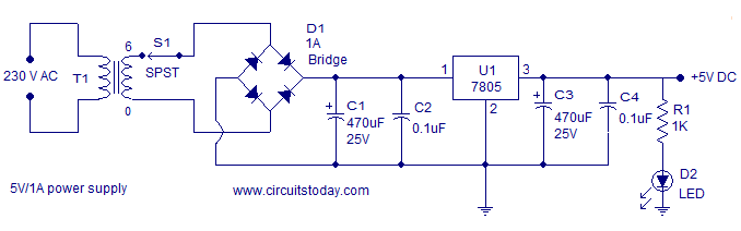
Power supply.
A simple 5V/1A regulator power supply that can be used for powering this circuit is shown below. This power supply is based 6V transformer, full wave bridge rectifier and a 7805 regulator.
 Notes.
The value of crystal X1 is very crucial in this circuit. Its value must be precisely 11.0952 or its integer multiples. Any values other than this will give erroneous results.
1 Comment
sir we need climatology flight landing circuit plzzz…