Interfacing dot matrix LED display to 8051 microcontroller.
LED dot matrix display.
An LED dot matrix display consists of a matrix of LED’s arranged in a rectangular configuration. The desired character or graphics can be displayed by switching ON /OFF a desired configuration of LED’s. Common display configurations available are 7×5, 8×8, 7×15, etc. LED dot matrix can be used in simple display applications where the resolution is not a big concern. The figure below shows the arrangement of LEDs in a typical 7×5 dot matrix display.
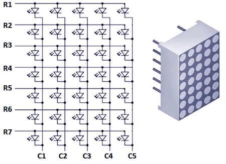
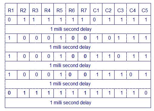
Any individual LED or a group of LEDs in the matrix can be activated by switching the required number of rows and columns. For example, in the above figure if Row1 is made high and Column1 is made low, the top left LED (address R1C1) will glow. As a demonstration, lets see how we can display letter “A” using the display. The tables given below shows the logic levels at each pin for displaying A.
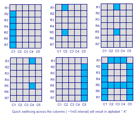
In the above diagram you can see that only one LED in a row will be ON at a time but any number of LEDs in a column can be ON at a time. That means the microcontroller’s port pin can directly drive a row but it requires additional circuit for driving the column lines. The circuit diagram for interfacing dot matrix display and 8051 microcontroller is shown below.
Circuit diagram.
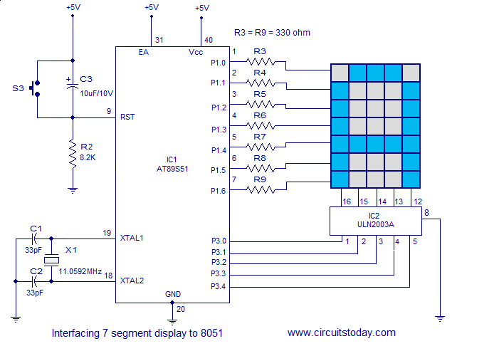
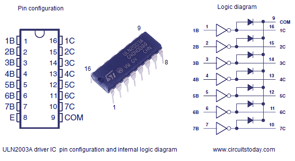
ULN2003A driver IC.
The purpose of ULN2003A here is to drive the column lines of the display. ULN2003A is a high voltage (50V), high current (500mA per channel) darlington transistor array. Each IC has 7 channels with individual output clamp diodes. ULN2003A an active high device, which means a logic high must be applied to the input to make the corresponding output high. The input pins are designated as 1B, 2B, 3B, 4B, 5B, 6B, 7B while corresponding output pins are designated as 1C, 2C, 3C, 4C, 5C, 6C, 7C. The pin configuration and simplified internal logic of ULN2003A is shown in the figure below.
Program.
ORG 00H
MOV P3,#00000000B        // initializes port 3 as output port
MOV P1,#00000000B        // initializes port 1 as output port
MAIN: MOV P3,#01111110B
      MOV P1,#11111110B
      ACALL DELAY
      MOV P3,#00010001B
      MOV P1,#11111101B
      ACALL DELAY
      MOV P3,#00010001B
      MOV P1,#11111011B
      ACALL DELAY
      MOV P3,#00010001B
      MOV P1,#11110111B
      ACALL DELAY
      MOV P3,#01111110B
      MOV P1,#11101111B
      ACALL DELAY
      SJMP MAIN         // jumps back to the main loop
DELAY: MOV R6,#255D     // 1ms delay subroutine
HERE: DJNZ R6,HERE
      RET
END
16 Comments
hello sir, i was asked to design a dot matrix display system as a project in school and would really need assistance…… please contact me at the email above
Hello,
I am experiencing difficulties programming the PIC and i am running out of time to complete my project, is there any chance in getting the PIC pre-programmed by a company or by the creator of this project.
Thank you.
hello sir, i made dot matrix display , but now i want to scroll alphabet{A)
SO HOW IT IS POSSIBLE , what do i need to change in asm program , plz help me.
to scroll u will need shift data byte from one ram location to another and then display the ram data on display and repeat this process
Seetharaman, can i replace ULN2003A with CSC2003 or CD2003
thanks for such a nice project,
how can i interface multiple dot matrix . please tell me.
hello. please give a programs in Embedded C language
cool… helped a lot… thanks circuitstoday… please keep updating with modern devices…
hy, i make dot matrix display and run same code which u wrote but it was not working , all leds were just on can u help me plz , rply me quick
i made aproject on led base scrolling disply please give me 8*8 a to z hex code
I must build a 8051 project for my class.
At first I wanted a led message board (6X26), but then wanted a simpler project.
Then I thought I’d try some sort of home alarm/indoor, outdoor light control/room occupancy. All, via keyboard, remotely interactive.
Now after seeing your “interfacing dot matrix LED display to 8051”
I want to make it my first ever programed 8051 project.
It may not be worth writing home about but, its close to my current realm of knowledge. I need to get clarification on the programming steps from a friend in my network as I don’t fully comprehend the hex instruction.
So thanks…for doing what you do.
I have maybe 5 weeks to get’er done.
I’ll need to assemble everything, so, if you have any recommendations, feel free to contact me.
Thank you for opening this website.
very good publication where even I may be able to contribute for you, such a good technical description.
In which software I use to write 8051 program?
I used MCU8051IDE for writing,testing and hex file generation. You can also use MIDE-51 or anything like that. In system programming was used for burning the hex file into microcontroller. ISP programmer kits are readily available in the internet stores. Just google for it.
Thnx very much 🙂