LED matrix displays can be used to display almost anything. Most modern LED sign boards uses various types of matrix boards with controllers. In this tutorial we are going to interface a single color 8×8 LED matrix with Arduino and display a few characters in it.
8×8 matrix consists of 64 dots or pixels. There is a LED for each pixel and these LEDs are connected to total of 16 pins. You can identify the pin out and circuit diagram of it using the following figure.
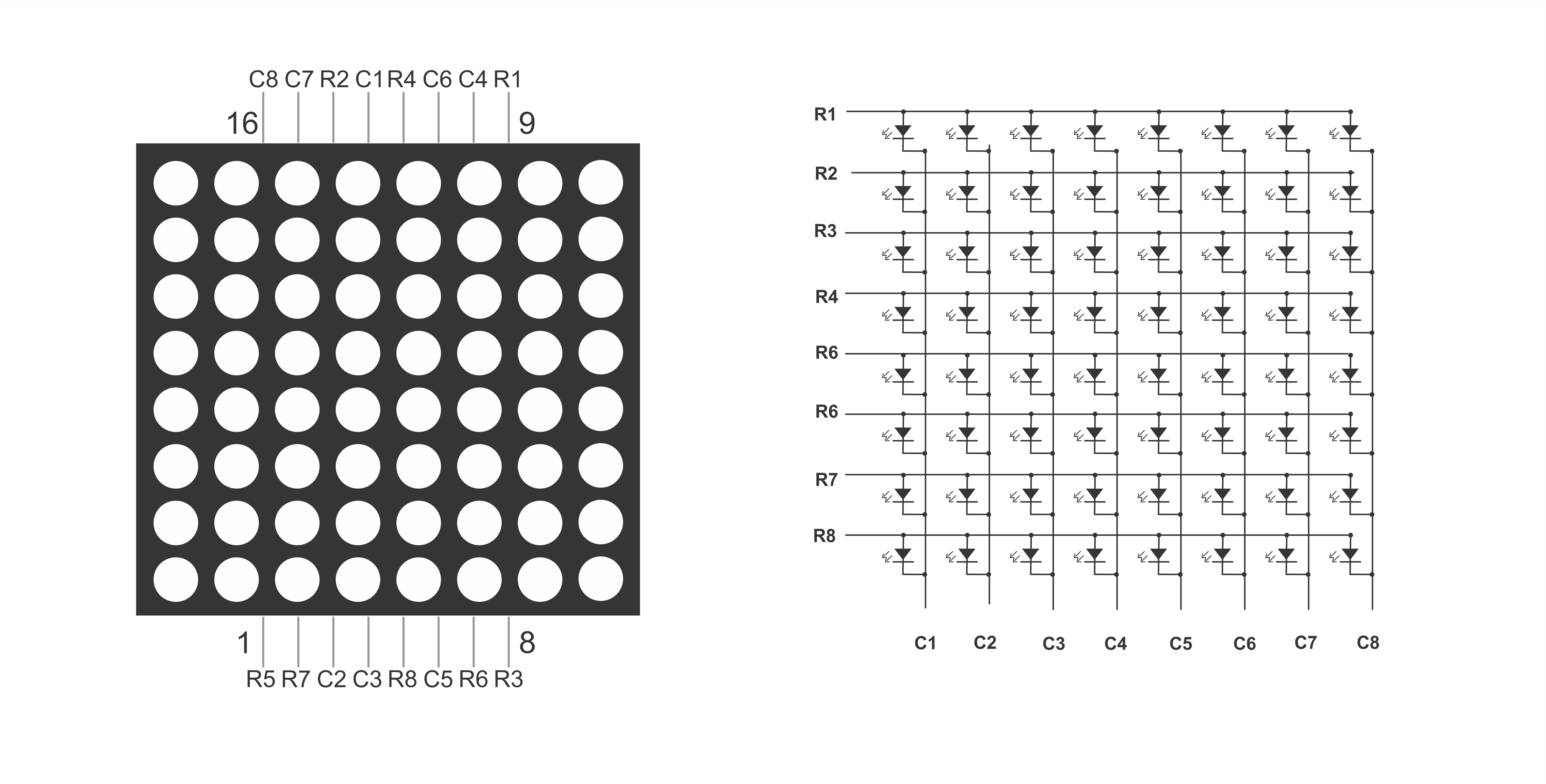
C1 – C8 – Column pins
R1 – R8 – Row pins
As you can see all anodes of same row is connected to one pin and all cathodes of same column are connected to another pin.We have 8 row pins and 8 column pins. If a positive voltage is applied to R1 pin and negative to C1, we can see that the first pixel turns on. If we apply negative to C2 then the second pixel turns on. Like this we can turn each pixel by hanging the supply pins. However we have 64 supply combinations, and doing it manually is practically impossible. This is why Arduino is interfaced with the 8×8 matrix.
Circuit Diagram
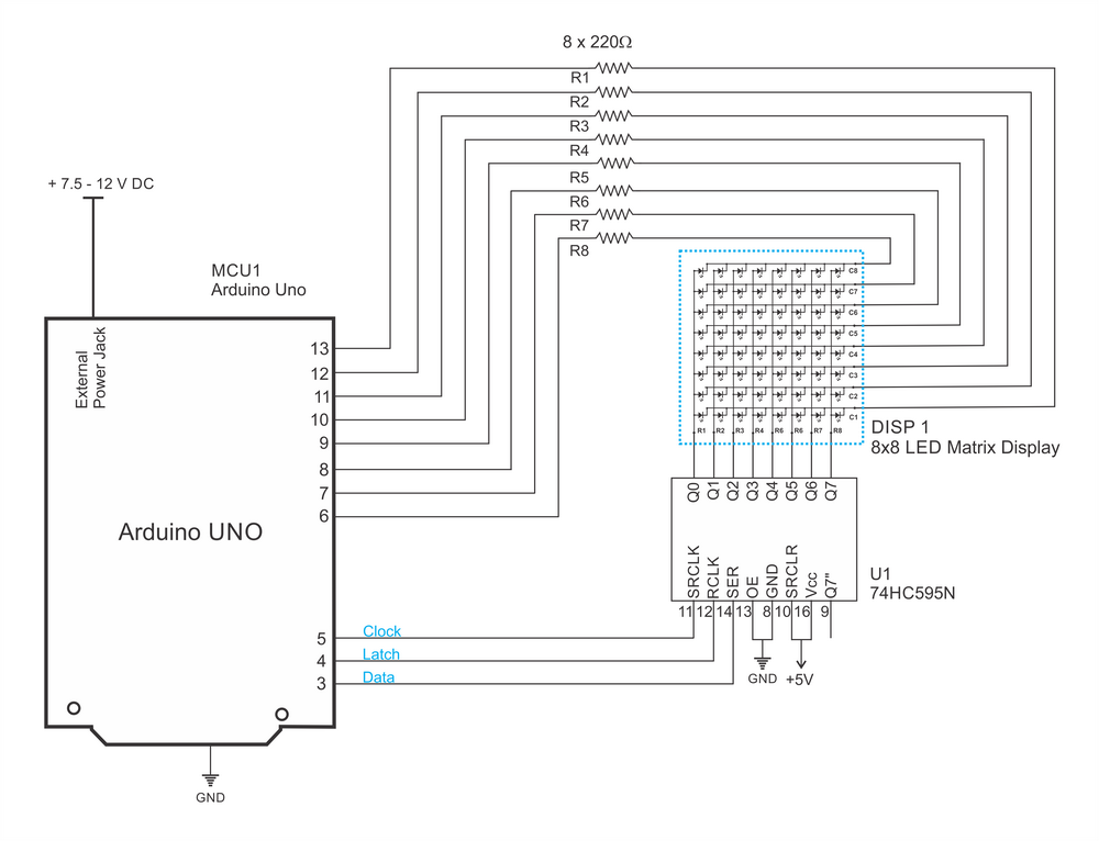
As you can see in the diagram every column pin is connected to Arduino pin through a 220Ω resistor. All the row pins are connected to one of the output pin of the shift register. The characters are displayed using the multiplexing techniques. Shift register is connected to Arduino as usual by data, latch and clock pins.
Arduino Code
 int latchPin = 4; // pis connected to shift registors
int clockPin = 5;
int dataPin = 3;
int pins [8] = {6, 7, 8, 9, 10, 11, 12, 13}; // common cathode pins
byte A[8] = {   B00000000, // Letters are defined
                B00011000,// you can create your own
                B00100100,
                B01000010,
                B01111110,
                B01000010,
                B01000010,
                B00000000
            };

byte B[8] = {     B00000000,
                  B11111100,
                  B10000010,
                  B10000010,
                  B11111100,
                  B10000010,
                  B10000010,
                  B11111110
            };

byte blank[8] = { B00000000,
                  B00000000,
                  B00000000,
                  B00000000,
                  B00000000,
                  B00000000,
                  B00000000,
                  B00000000
                };
byte R[8] = {  B00000000,
               B01111000,
               B01000100,
               B01000100,
               B01111000,
               B01010000,
               B01001000,
               B01000100
            };


void setup() {
  Serial.begin(9600); // Serial begin
  pinMode(latchPin, OUTPUT); // Pin configuration
  pinMode(clockPin, OUTPUT);
  pinMode(dataPin, OUTPUT);
  for (int i = 0; i < 8; i++) { // for loop is used to configure common cathodes
    pinMode(pins[i], OUTPUT);
    digitalWrite(pins[i], HIGH);
  }

}

void loop() {


  for (int k = 0; k < 1000; k++) { // showing each letter for 1 second
    display_char(A);

  }

  for (int k = 0; k < 1000; k++) {
    display_char(B);

  }
  for (int k = 0; k < 1000; k++) {
    display_char(R);

  }

  // add more letters show method here


}
void display_char(byte ch[8]) { // Method do the multiplexing
  for (int j = 0; j < 8; j++) {
    digitalWrite(latchPin, LOW);
    digitalWrite(pins[j], LOW);

    shiftOut(dataPin, clockPin, LSBFIRST, ch[j]);
    digitalWrite(latchPin, HIGH);
    //delay(1);
    digitalWrite(latchPin, LOW);
    shiftOut(dataPin, clockPin, LSBFIRST, B00000000); // to get rid of flicker when
    digitalWrite(latchPin, HIGH);
    digitalWrite(pins[j], HIGH);

  }


}
Code Explanation
In the code all important lines are commented. The digitalWrite command is used for controlling the column pins and shiftOut command is used to write to shift register. Letters are defined in a byte array when the characters displaying 0 are OFF and 1 is ON. This way you can define your own letters or symbols. In the multiplexing method shiftOut(dataPin, clockPin, LSBFIRST, B00000000); line is used to reduce the flicker by turning off all the pixels after each step.
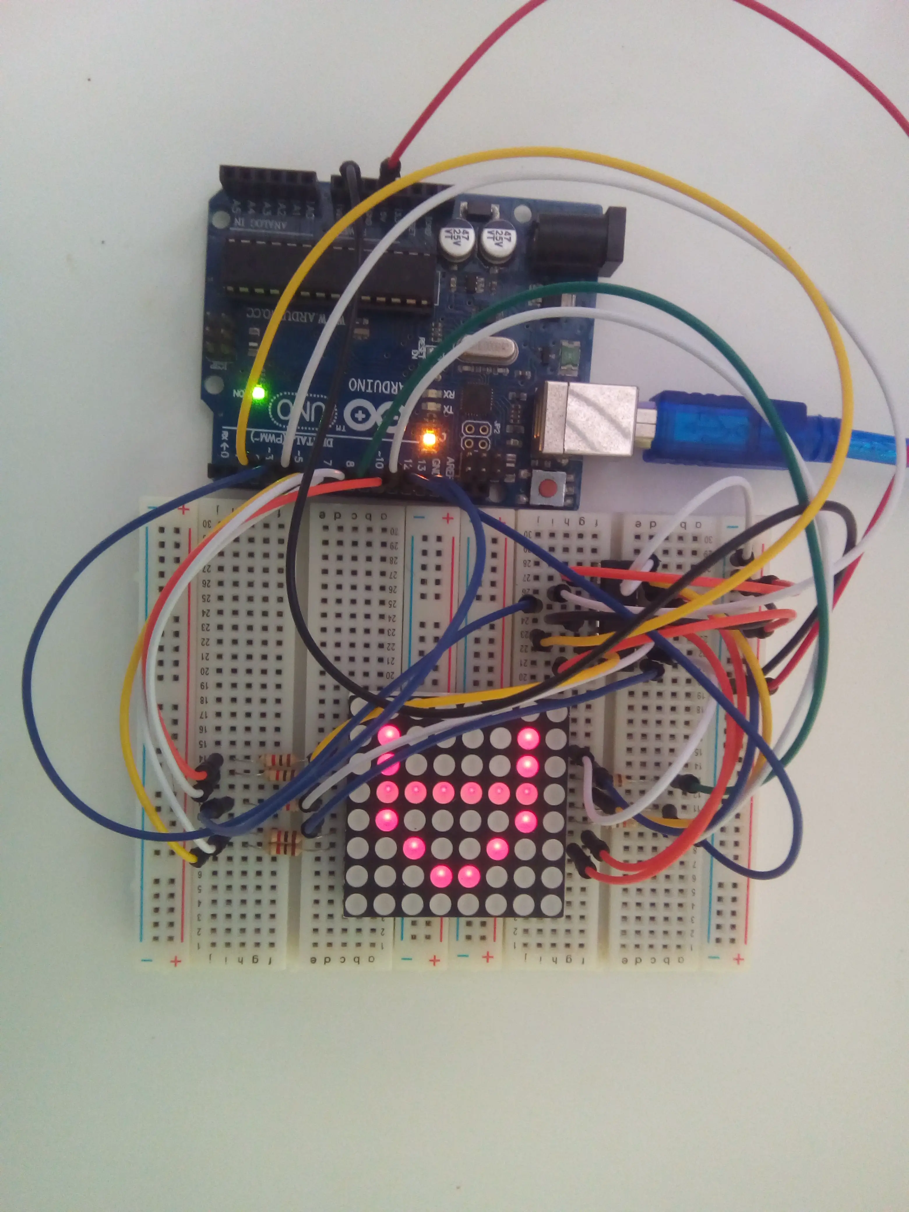
Breadboard Configuration
You can see the actual bread board setup in the following figure.
8 Comments
Hello,
Can you please explain why R1, for example, is connected to pin 9? Why doesn’t it connect in order? R1 to pin 1, R2, to pin 2, R3 to pin 3 and so on. It is important to me to understand these connections between pins and rows/columns because I don’t want to accumulate gaps in my learning. If you say it’s up to the manufacturer, then please direct me to one.
Have a nice day!
How can i add more letters?
What program changes are required if the 74HC595 needs to have active LOW outputs and the ATmega328p needs to be active HIGH outputs?
My matrix is common anode, what do I need to do differently compared to your common cathode version?
What type of Arduino was used here pls?
arduino uno
Can we program this to display a flickering flame ,like “Moma Flame lamp”?
This lamp I saw in the Museum of modern arts,New York which also used the Arduino.
If yes what will be the Arduino code?
@Naved – No! You should follow a different approach.