Intercom circuit with ringer
Description.
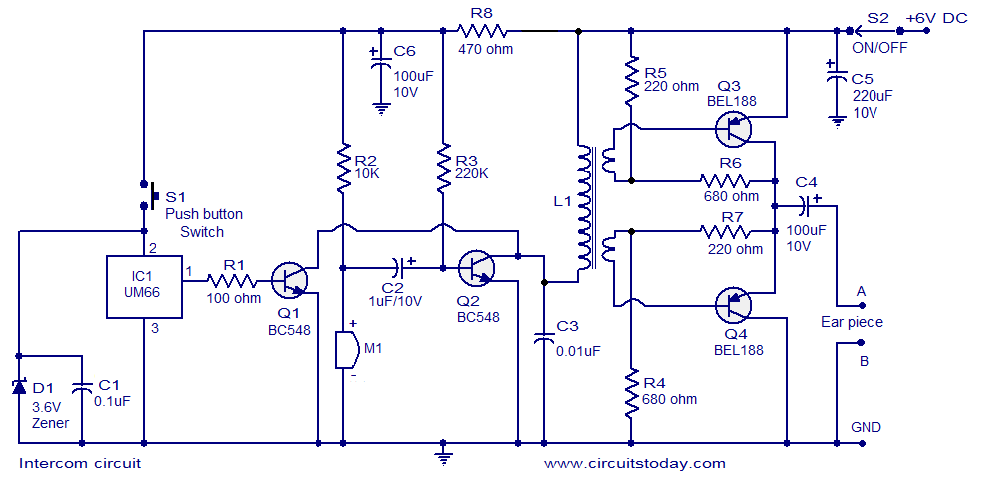
A simple intercom circuit designed based on transistors is shown here. This intercom circuit does not require a changeover switch and you can use it just like a telephone and a ringer circuit is also included.
IC1 UM66 and transistor Q1 forms the ringer section. When pushbutton switch S1 is pressed UM66 produces a musical tone. This tone is amplified by Q1 and is coupled to the collector of Q2. Condenser Mic M1 is used to pick the conversation and Q2 is used to amplify it. R2 powers the condenser Mic while C2 is the DC decoupling capacitor for the amplifier stage based on Q2. The next stage of the circuit is a transformer coupled push pull amplifier stage based on L1, Q3 and Q4. Capacitor C5 is the power supply filter while capacitor C4 couples the output of the push pull amplifier to the ear piece.
Circuit diagram.

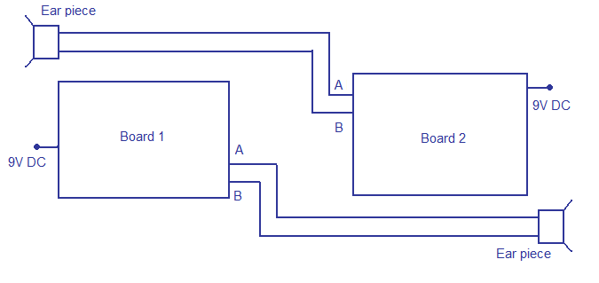
Connection diagram.

Notes.
-
Assemble the circuit on a vero board.
-
Use 9V PP3 battery for powering the circuit.
-
The earpiece can be a telephone ear piece.
-
L1 can be a 6V audio driver transformer.
-
S1 is a pushbutton switch while S2 is a ON/OFF switch.
-
Make two identical circuits as per the circui diagram and arrange them as shown in the connection diagram.

10 Comments
plz give me the pcb layout,theres some problem in our circuit
how we connect digital switches in intercom circuit ??????
Thanks 4 that cct. Pls what is primary and secondary turn of L2. Pls give methe detail
Primary 600turns of 32 SWG super enameled copper wire secondary 200turns of same wire bifiller wound over primary with a CRGO grade lamination of min 2 sq centimeter center limb. Ensure start and finish of the winding’s are marked. If the secondary winding start finish are interchanged the output sound will be low and distorted by interchanging start finish of one of the winding will make the sound reproduction good and loud.
Who uses an earpiece with an intercom? Rather than try to find L1, wouldn’t it be easier to use an LM386 for the amp and then it could drive a speaker. Incidently, a walkie-talkie would require several tuned circuits, which would be too complicated for most builders.
Hi Muzammil this is a wired intercom with 4 core cable connecting both the units.
can provide me the walkie talkie circuit diagram
is these circuit is wirless if than wht is it range plz reply fast