Testing triac using a multimeter.
A multimeter can be used to test the health of a triac. First put the multimeter selector switch in a high resistance mode (say 100K), then connect the positive lead of multimeter to the MT1 terminal of triac and negative lead to the MT2 terminal of triac (there is no problem if you reverse the connection).The multimeter will show a high resistance reading (open circuit).Now put the selector switch to a low resistance mode, connect the MT1 and gate to positive lead and MT2 to negative lead. The multimeter will now show a low resistance reading (indicating the switch ON).If the above tests are positive then we can assume that the triac is healthy. Anyway this test is not applicable triacs that require high gate voltage and current for triggering.
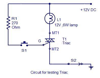
Circuit for testing a triac.
This is another approach for testing a triac. Almost all type of triacs can be tested using this circuit. This circuit is nothing but a simple arrangement to demonstrate the elementary action of a triac. Connect triac to the circuit as shown in circuit diagram and switch S2 ON. The lamp must not glow. Now press the push button switch S1.The lamp must glow indicating the switching ON of triac. When you release the push button, you can see the lamp extinguishing. If the above tests are positive you can assume that the triac is healthy.


16 Comments
Yes now it is ok and working Mt2 and Mt1 must be reversed otherwise it is not working I was tried many times I would like to thanks all of you for the tips.
hi abdolkarim.i excheange the mt1 with mt2 and instead of L1 I use an led with 1 k resistor.when h triggered the gate by switch S1 the led go on .but when I release the S1 the led is going to off…I espected when I released the push button S1 the led be on…please help me
thanks Greg
Please correct the diagram. Greg is correct. The drive must go from MT2 to G.
Wish I’d read the comments first! Spent some hours trying to see what I’d done wrong….and it wasn’t me at all. I (partially!) agree with Greg….correct the diagram.
The triac test circuit shown is incorrect and will not work as shown. MT1 and MT2 are labelled back to front. MT2 should be at the top and MT1 at the bottom, next to the gate G. If wired that way it will work correctly. But you cannot trigger the gate by connecting it to the same potential as MT1. Please research this point and correct the fucking diagram, you retards, instead of wasting peoples time. Thank you.
I see. Great step by step instruction.
Oh wait, it works again with the TIC206, I accidentally connected the direct 12v wire to the bulb (top centre vertical wire) behind the resistor instead of in FRONT. 😉
Now, in this same setup the ACS triacs only works when I close S2.
They are definately different.
I have test this circuit with a TIC206M triac.. in first instance it worked like described (light on with S1 and S2 closed) but now the light only stays on when I first close S1 and S2 AND open S1, thus when closing S1 and S2 the light will go on; S1 now acts as the light switch.
Also, I have test this circuit with a STmicroelectronics ACS085S and an ACS102S but neither works. Are these some other types of triacs, in behaviour or so, than the TIC206 ones?
IIRC the description of the test circuit has an error: for DC current, after you press and release S1, the lamp stays on until you break the circuit by opening S2.
If the input is AC or pulsed DC, the lamp stays on while S1 is held closed, and then turns off at the next zero-crossing – i.e., the triac disarms when the current flowing from the main terminals goes below a certain limit.
thanks….
I agree with the previous comments. MT2 label should be at the top and MT1 label at the bottom side with the gate. Trigger voltage in phase with MT2 (at top) to allow triac to operate in the first and third quadrants when AC is normally applied.
Eric, MT1 and MT2 have to be reversed, as you say. I just tested it on an actual part..
Thanks for pointing out.
Aren’t MT1 and MT2 reversed in both this drawing and the test description? I’ll admit that I’m brand new to understanding triacs, but every other book and website I’ve found shows MT1 and the Gate on one side and MT2 on the other side. I’ve only found one other description of testing triacs, but it described joining MT2 with the gate on one probe and putting the other probe on MT1. I’d really like to know how to reliably test triacs. Are there triacs configured in different ways regarding MT1/MT2 designations, or was this just a typo? Thanks for your help!