Gesture Controlled Robot Using Raspberry Pi
Have you ever tired of controlling everything with buttons? Thought of controlling something with simple hand movements by sitting on your lazy couch? If yes, then you are at the right site. In this tutorial we are going to control a robot driven by two DC motors by simply using hand movements. There are different kind of sensors to detect your hand movement like flux sensors, Accelerometers and other gravity based sensors. So for wireless transmission we are going to use RF 434 module which transmit 4 bit data. 4 bit data means you can transmit 16 different combinations i.e., 0000 to 1111. Further in this tutorial we will use an encoder and decoder to avoid interference in the air interface. A motor driver will drive the motors from using the decoder data.
We use our Raspberry pi at the transmitter end to analyze the sensor data and to transmit a data combination to the motor driver to drive the motors accordingly so that the robot can hover around. We will be using a 12 V battery on robot to power the decoder module, receiver module and the motors. At the transmitter end sensors and transmitter encoder module is powered by raspberry pi itself.
Components
| Components | Specification | Quantity |
|---|---|---|
| Raspberry Pi | Version 3 | 1 |
| Memory Card | More than 8 GB | 1 |
| Accelerometer | ADXL 345 or MPU6050 | 1 |
| RF Module | RF Tx and Rx 434 | 1 |
| Power supply | 5 V mini USB adapter for Rpi 12 V Battery for Robot | 1 |
| Wires | Female to male & Male to female | 10 each |
| Encoder | HT12E (prefer Module) | 1 |
| Decoder | HT12D (prefer Module) | 1 |
| Motor Driver | L293D (prefer Module) | 1 |
Gesture Controlled Robot Using Raspberry Pi – Block Diagram
Transmitter End
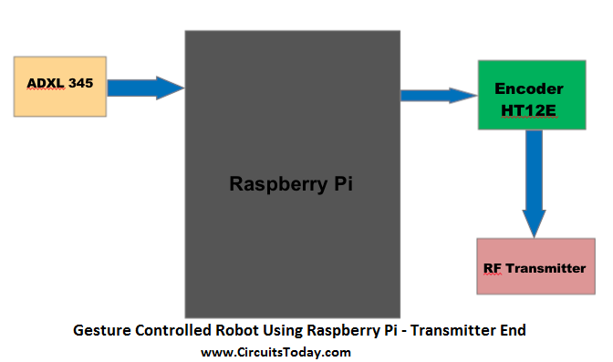
In transmitter side we have Accelerometer, raspberry pi , encoder module and RF transmitter. The gesture data flows from accelerometer to the raspberry pi and there it is processed to decide the movement of the robot and the data for motion is transferred to the encoder module via GPIO pins. The encoder module encodes the data and transmit into air interface with the help of RF transmitter.
Gesture Controlled Robot Using Raspberry Pi – Receiver End
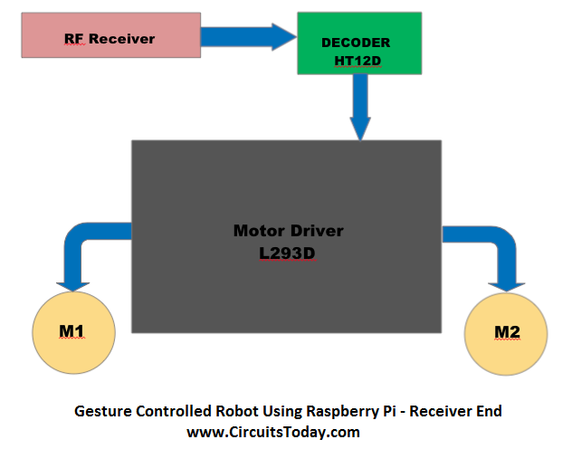
The RF receiver from the receiver end gets the data from the air interface and gives it to the decoder module. The decoder module decodes the received data and provides it to the motor driver L293D. From the motor driver the motors are driven according to the gesture data.
Accelerometer
Aceleration is the measurement of the change in velocity, or speed divided by time. For example if a car moves from rest 0 to 60 Km/hr in 10 seconds, the car is accelerating at 6Km/hr. So what it has to do with my hand gesture?
An accelerometer is an electromechanical device used to measure acceleration forces. Such forces may be static, like the continuous force of gravity or, as is the case with many mobile devices, dynamic to sense movement or vibrations. By measuring the amount of static acceleration due to gravity, you can find out the angle the device is tilted at with respect to the earth. By sensing the amount of dynamic acceleration, you can analyze the way the device is moving.
Some accelerometers use the piezoelectric effect -they contain microscopic crystal structures that get stressed by accelerative forces, which causes a voltage to be generated. Another way to do it is by sensing changes in capacitance. If you have two microstructures next to each other, they have a certain capacitance between them. If an accelerative force moves one of the structures, then the capacitance will change. Add some circuitry to convert from capacitance to voltage, and you will get an accelerometer.
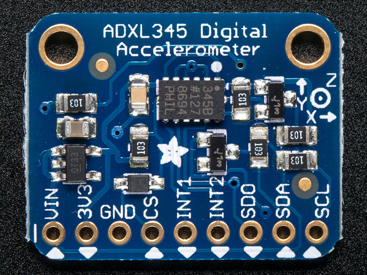
Accelerometers are low power devices which output acceleration in the form of Analog voltage and some accelerometers in digital form. Analog accelerometers like ADXL 335 gives you 3 analog output X,Y,Z base on the axis of your movement. You can convert these analog voltages into digital voltages by means of an ADC. Digital accelerometers such as ADXL345 will communicate through SPI or I2C protocols. This have less very noise and most reliable
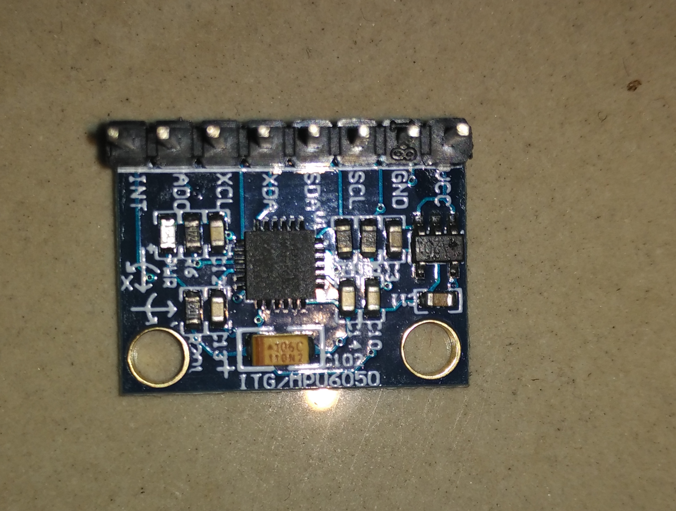
There is another sensor MPU6050 which has both accelerometer as well as gyroscope in it. That can also be used in place of accelerometer. The address of ADXL345 and MPU6050 differs while connecting in I2C mode with raspberry pi, for ADXL 0x53 and MPU it is 0x68. In this tutorial i’ll explain how to use both ADXL345 and MPU6050.
Interfacing Accelerometer
Now we will interface our accelerometer ADXL 345 and MPU 6050 to our raspberry pi and check the readings of the sensor. I believe your raspberry pi is installed with latest operating system and python in it, since we are going to use python code here.
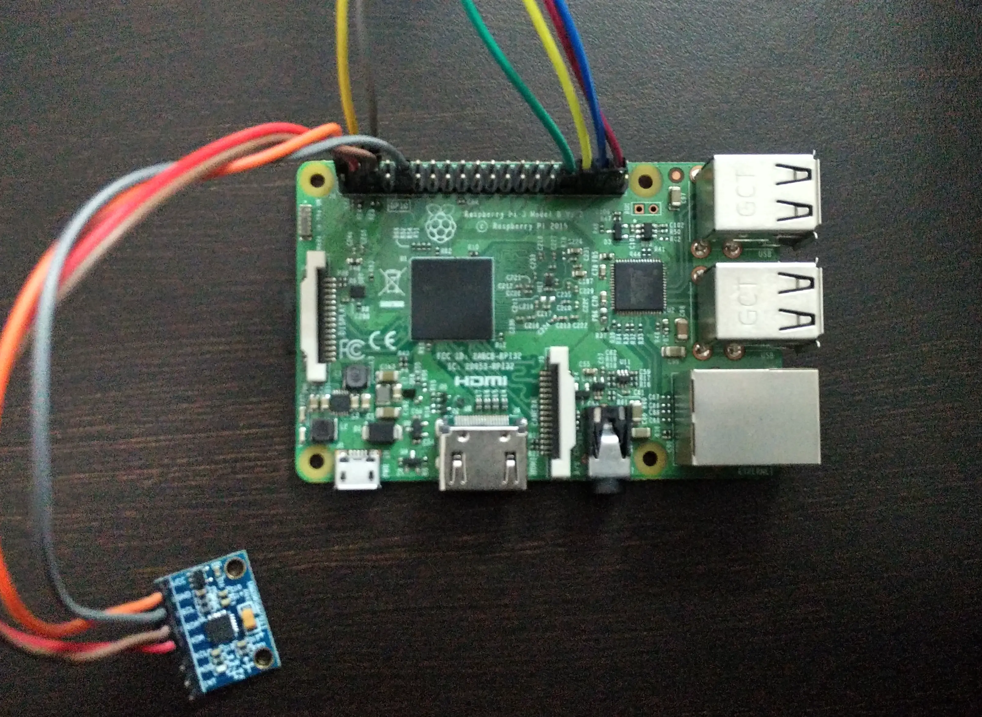
Lets connect ADXL345/MPU6050 to our raspberry pi. Here we are going to use I2C protocol to communicate between devices. In I2C protocol the data is transferred via SDA(Serial Data ) and clock in SCL (Serial Clock) . It is asynchronous half duplex communication protocol. The Master controls the whole process and slaves responds according to master commands. Data rate is determined by the slave’s capable frequency. There are only 4 connections between master and slave here 3V, Gnd, SCL and SDA .
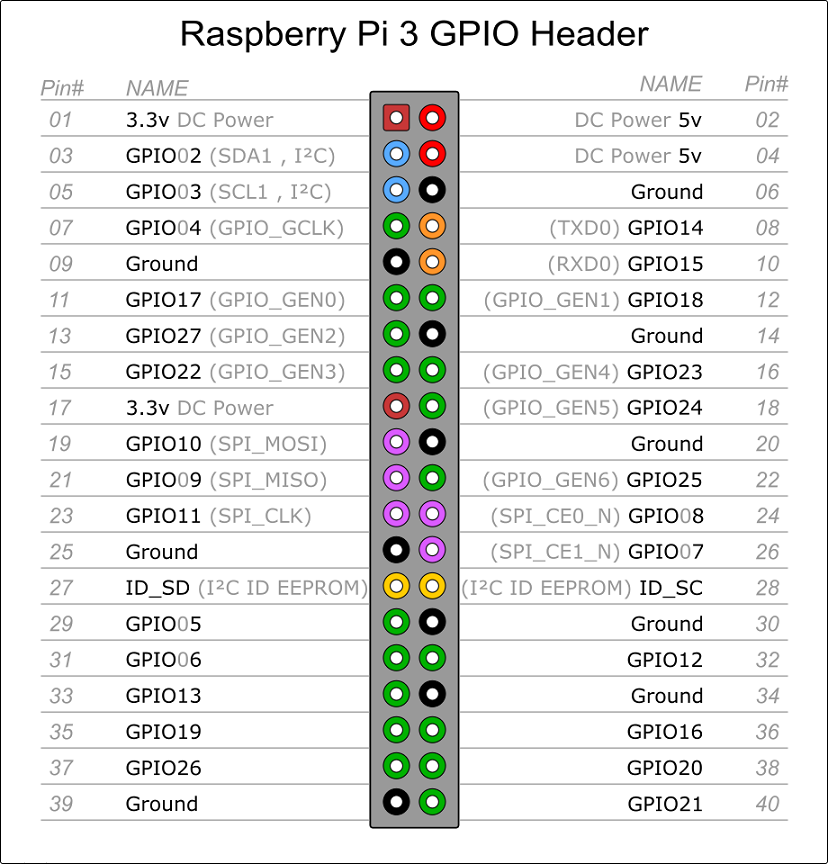
From the GPIO pin out diagram you can see the SDA and SCL pins on Rpi and connect it to the ADXL345/MPU6050 SDA and SCL pins respectively. Power the sensor using RPi itself. Now the connections are done.
Before testing the sensor let’s install python-smbus for I2c protocol in rpi and enable the I2C protocol in our RPi.
Installing smbus:
sudo apt-get install python-smbus i2c-tools
Enabling the I2C in RPi:
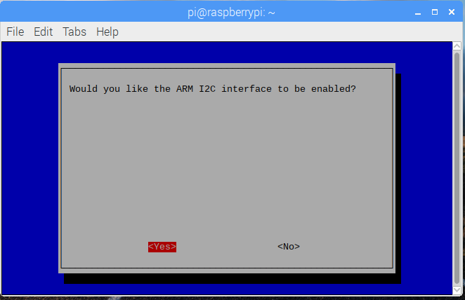
sudo raspi-config
Go to interface options and enable I2c protocol.
Then include the i2c specification lines by these commands.
sudo nano /etc/modules
Add these lines
i2c-bcm2708
 i2c-dev
If you’re using a old rpi remove i2c from backlist by using these commands
sudo nano /etc/modprobe.d/raspi-blacklist.conf
Comment out (#) blacklist i2c-bcm2708
sudo reboot
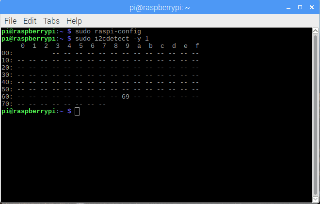
Test the connection by using this command. This will show the address of the sensor connected to our pi.
sudo i2c detect -y 1
Adxl will be found in 0x53 and Mpu will be found in 0x68 or 0x69
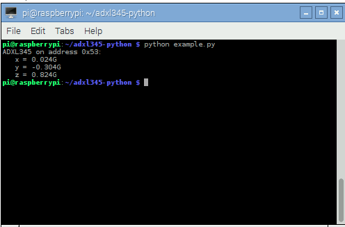
Now we will download a pre-written library for ADXL345 for pi in python from Github and test the sensor output. Use these commands.
git clone https://github.com/pimoroni/adxl345-python
 cd adxl345-python
 sudo python example.py
Example.py is the program which outputs the X,Y and Z values as shown below.
We can modify this program or use this for our project.
For MPU6050 pimoroni program wont work, so we will use a different python module from github.
By using these commands.
git clone https://github.com/Tijndagamer/mpu6050.git

cd mpu6050

python setup.py install
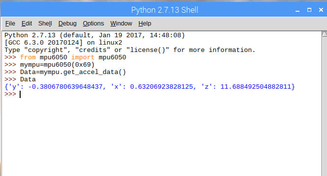
To check our sensor connection and address open terminal and type the command below. It will show the sensor address at 0x68 or 0x69 as shown below.
And to test our sensor data go to the python editor and type these commands only by one to see the sensor output.
from mpu6050 import mpu6050

mympu=mpu6050(0x69 )

Data=mympu.get_accel_data()
A step further you can now determine the threshold values of 4 different position for the movement of right, left, forward and backward and note it down. Calibration can be done based on your sensor values at different positions like keep it in a position which you want for the forward movement and note down 5 similar values and round it off to a threshold, so that if the sensor crosses the rounded off value a condition statement in the program can be enabled. Similarly calibrate it for all other movements like left, right ,back and stop.
Program/Code
Note: The code is explained in the comments itself.
Transmit Data
Now the python program will output the 4 digital outputs according to the threshold value calibrated to the gesture motions/positions. If it exceeds the threshold, the digital output corresponding to the motion will be assigned to GPIO pins.
Now the GPIO pins which are assigned for digital outputs are connected to the encoder 4-bit data pins. The encoder is connected to the RF transmitter. Prefer Encoder module along with Transmitter as shown below.
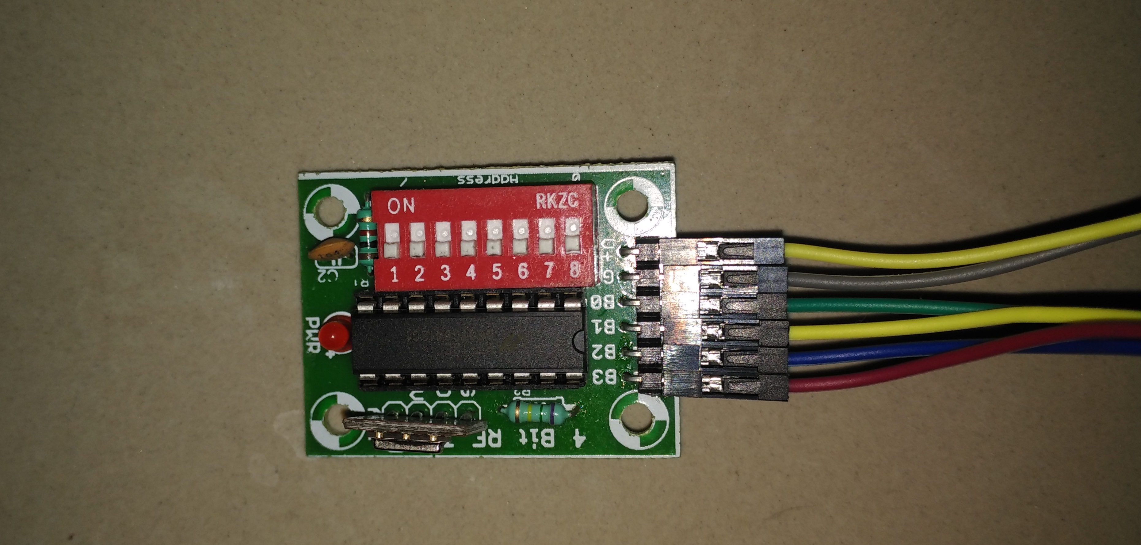
Power the transmitter module using rpi itself. RF transmits the data serially to the receiver. In transmitter module there are 8 switches for encryption . The same switch positions has to be set in the receiver to receive the data correctly.
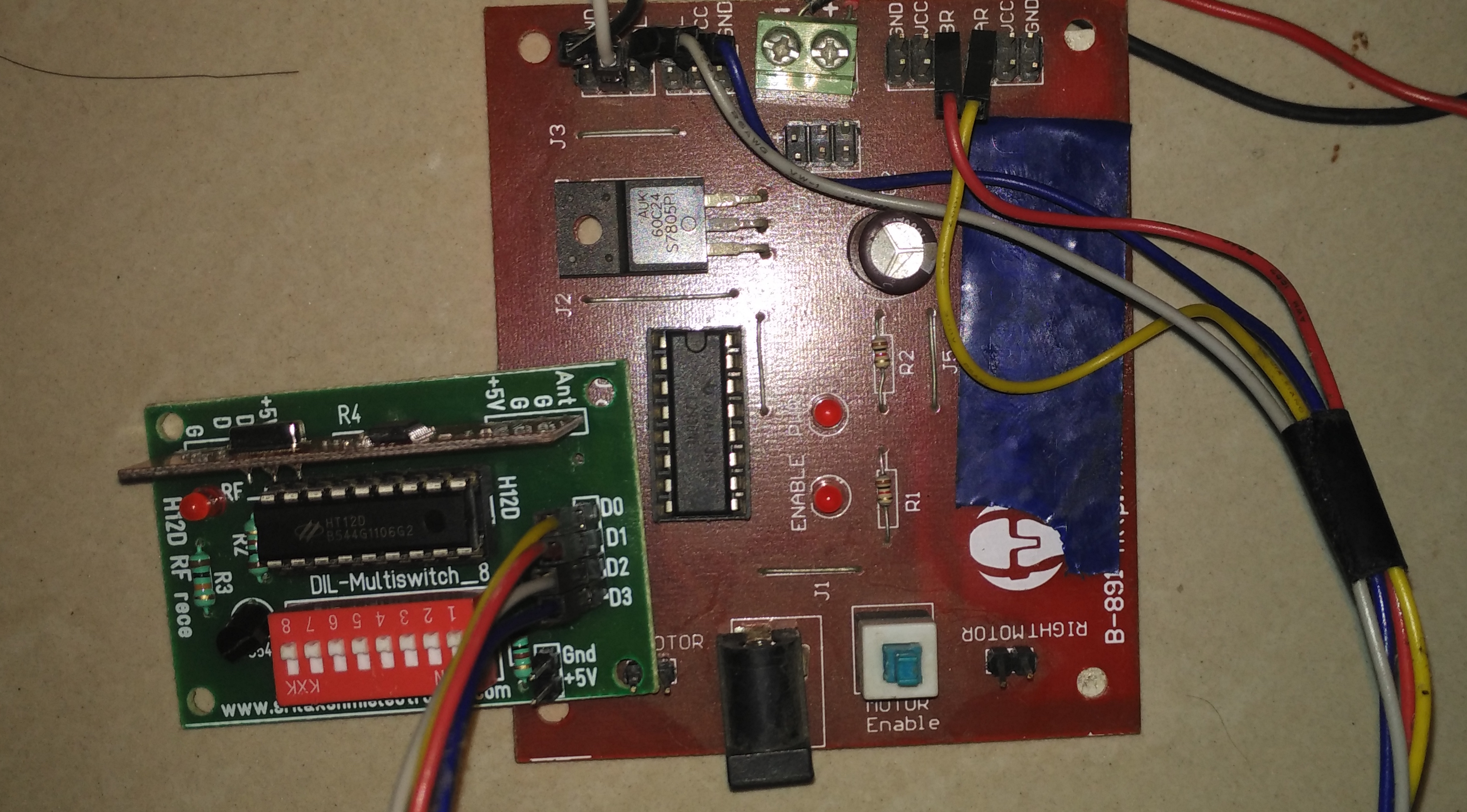
Receive Data
Once the transmitter module is started transmitting the motion data, power on the Receiver module from the battery which we will be using for the Robot. How to test if the receiver is receiving data or not. While powering the Rx module two LEDs will be lit one for power and another one for connection enabled. If connection is not enabled, check the switch positions and transmitter module.
Before connecting the decoder to the motor driver lets cross check the received data with a Multi-meter. If you don’t have any multimeter connect those 4 pins of decoder output to any 4 gpio pins of rpi and add these lines of code to our transmitter program, later we comment it out.

Now we will print both motor output values to be transmitted via encoder and the data received from decoder from the air interface. These data should match.
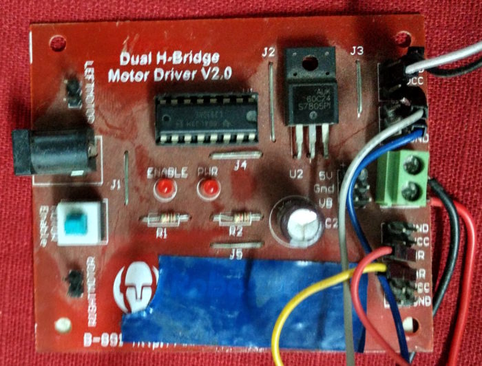
Data to Action
Once the data is matched we will connect our decoder to the motor driver L293D. The 4 pins of decoder is enough to driver the motor driver output which in turn amplify the decoder data to the motor. So that the motor runs as per the decoder data.
Since we are using 4 pins of decoder which can give 16 combinations of data, but 4 is enough to hover the robot. A single DC motor has two pins A and B (say). Either the pin A has to be in higher voltage than the other pin B so that it can make a potential difference to run the motor. The directions of rotation are reversed by reversing the connection. So two motors 4 pins and 4 decoder outputs will drive the motor.
You can consider Motor A pins as A+ A- and Motor B pins as B+ B- for your convenience.
Motor configuration
| Decoder Output A1A2B1B2 | Motor A A1A2 | Motor B B1B2 | Robot Motion |
|---|---|---|---|
| 1010 | 10 | 10 | Forward |
| 0101 | 01 | 01 | Backward |
| 1001 | 10 | 01 | Right |
| 0110 | 01 | 10 | Left |
For moving forward both the motors should rotate in same direction either in clockwise or anticlockwise. For backward movement the exact opposite of forward data should be given to make the motors to rotate in opposite direction.
For moving the robot left and right, one wheel should rotate in clockwise and another in anticlockwise so that it will turn your robot towards left or right depending on your configuration.
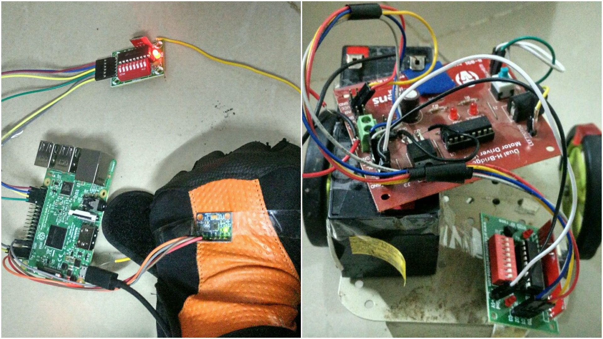
Once the configuration is done, lets test drive our robot using our hand gestures. Power on all the modules and send data of your hand gestures using the sensor via RF to the Motor driver. Based on your hand gesture robot will move with a delay of milliseconds as you see in demo.
This is testing the accelerometer by fixing in the hand and changing the orientation of hand, so that based on the threshold values, it will print the motions as LEFT, RIGHT, FORWARD or BACKWARD. Better view it in a full screen.
Since the wires are tangling and i’m not having an antenna, the motion wont be that smooth. But those can be fixed.
3 Comments
Can I have a video about this project .. Means how to make it .. Connect the wires n all..
how will I get wiring details of the circuit.
Like it