Description.
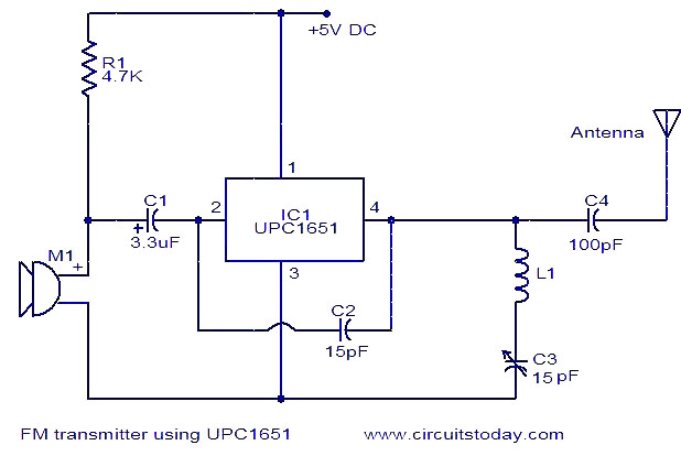
Here is the circuit diagram of an FM transmitter using the IC UPC1651. UPC1651 is a wide band UHF Silicon MMIC amplifier. The IC has a broad frequency response to 1200MHz and power gain up to 19dB.The IC can be operated from 5V DC.
The audio signals picked by the microphone are fed to the input pin (pin2) of the IC via capacitor C1. C1 acts as a noise filter. The modulated FM signal will be available at the output pin (pin4) of the IC. Inductor L1 and capacitor C3 forms the necessary LC circuit for creating the oscillations. Frequency of the transmitter can be varied by adjusting the capacitor C3.
Circuit diagram with Parts list.
Notes.
- The circuit can be assembled on a Vero board.
- Inductor L1 can be made by making 5 turns of 26SWG enameled copper wire on a 4mm diameter plastic former.
- A ¾ meter insulated copper wire can be used as the antenna.
- Do not give more than 6V to the IC.
- Mic M1 can be a condenser microphone.


26 Comments
I am thinking about building this circuit, but i require some evidence or proof about its performance results for my general satisfaction to start with. Can anyone here tell me about its working probability?
Has anyone built this? Looking at the circuit, the tuned circuit part (L1 and C3) form a series tuned circuit which will exhibit it’s lowest impedance at resonance, thereby sending most of the output to ground.
I must be missing something here (probably something very simple) but it looks to me like this circuit could never work.
can we replace Mic M1 with a Audio input from a MP3 Player.
Can u let me knw the actual value of inductor?
where i connect the ground
10km fm transmetter circuits
thanks for giving it. i have a doubt how to recollect the transmitted signal at the reciever side pls give ciruit of Rx
mail id:rakeshd4d@gmail.com
By removing R1 you remove the bias given to mic. 5Volt supplies + should get connected Pin No 1 of IC and negative to Pin No3.
The L1 details are available in the notes as well the antenna ‘A’length.
what is the inductance of L1?
what inductace should have L1?
questions:
1) if i remove R1, +5V will alimentate only the IC.I am right?
2) where i put ground from +5V? at pin 3? in datasheet says at pin 3.
thank you.keep up the good work
Hi Andrew remove R1 and reverse the polarity of C1 and feed any audio information in place of M1.
can i put instead M1 audio from pc?
how much frequency it can generate
How long the range of “FM transmitter using UPC1651”?
مهدی
hi i want to ask if somene have a complete scenatics of a fm bug thanks
How can I get the UPC 1651 IC.Can’t get it in the local market,yet it correctly suits my project needs.”A powerfull CCT it is.”
i need this ic
where can i get UPC1651 ic
HiMoiz it will be around 150MHz with the recomended components.
hi,i want to know the operating frequency urgently.plz
the pdf for the chip..shows it’s a high uhf freq chip.
19db @ 500megs..and just a few parts…looks interesting…theres a schematic of this with the 7805 voltage reg on 9v here on the site someplace..
I build this and its range is only 10meters
i am going to make this. but i wanna know how long this will work.