Description.
Many fire alarm circuits are presented here,but this time a new circuit using a thermistor and a timer to do the trick. The circuit is as simple and straight forward so that, it can be easily implemented. The thermistor offers a low resistance at high temperature and high resistance at low temperature. This phenomenon is employed here for sensing the fire.
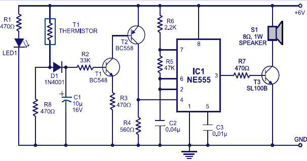
The IC1 (NE555) is configured as a free running oscillator at audio frequency. The transistors T1 and T2 drive IC1. The output (pin 3) of IC1 is couples to base of transistor T3 (SL100), which drives the speaker to generate alarm sound. The frequency of NE555 depends on the values of resistances R5 and R6 and capacitance C2. When thermistor becomes hot, it gives a low-resistance path for the positive voltage to the base of transistor T1 through diode D1 and resistance R2. Capacitor C1 charges up to the positive supply voltage and increases the the time for which the alarm is ON. The larger the value of C1, the larger the positive bias applied to the base of transistor T1 (BC548). As the collector of T1 is coupled to the base of transistor T2, the transistor T2 provides a positive voltage to pin 4 (reset) of IC1 (NE555). Resistor R4 is selected s0 that NE555 keeps inactive in the absence of the positive voltage. Diode D1 stops discharging of capacitor C1 when the thermistor is in connection with the positive supply voltage cools out and provides a high resistance path. It also inhibits the forward biasing of transistor T1.
Circuit diagram with Parts list.
Notes.
- The circuit can be powered from a 6V battery or a 6V power supply.
- Click Here ! for the circuit diagram of a power supply circuit for this project.
- The thermistor can be mounted on a heat resistant material like mica to prevent it from damage due to excessive heat.
- The LED acts as an indication when the power supply is switched ON.
Related Posts
53 Comments
I am actually making this for my eet project is anyone provide me the PCB board layout of this project.
on which temperature the thermistor will start to operate
Sir,
I am willing to learn about this project more deeply.Please help me.I have know about the schematic circuit diagram and also the PCB designs..Thank You…
I want to build a fire detector, I need help..
hyy why we use 555 ic in this circuit what is it main role and why we give positive voltage to pin 4 reset what is its reason and why we are using more than one capacitors and transistors
sir,
i would like to know why we use transistor T2 (BC558), why can’t transistor T1 provides the required positive voltage to the timer. why we need T2 ?
Take 1k thermister, supply 2.5 v,take R8 100ohms .I made these changes and it is working for me!!!
sir in this circuit, i used candle to heat thermistor…is that heat is enough to increase the temperature of thermister??…how to check the output?…what will be the voltages at pin 4,6,3 when heat is given?…
when i connect supply speaker starts sound
what should i do ??
Check whether any wires have been bymistakely shorted, And ensure that the diode is reverse biased
pleas tell me what type of thermister used in this project
Is there any transistor which I can use instead of the SL100B. & one more thing is fine to use 8ohms 2W speaker instead of 8ohums 1W speaker.
can you please replay me as soon as possible. Thank you
is there any replacement for IC NE555 & sl100b?
sir, can you explain how speaker make sound.
Is that the output signal from 555 timer amplified by T3 then passed to speaker?
or any other explanation.
is there any relay version of this circuit?
is there any replacement for sl 100b
Hi MBA you can use any medium power transistor like 2N1711, 8050, BD135 2N2219 etc
what is the brand/model/manufacturer of the Thermistor?Thanks
Hi,
There isn’t a particular branded product/or it is least known ;). Just ask for a thermistor at the shop and thats enough.
As Mr. seetharaman told, ask for a NTC thermistor.
hi sir………..
please answer my question
what transistor can i use replase sl100
i can not found sl100
tanks a lot
sorry, but can i replace the thermistor with lm35 ?
i tried, but the speaker alarmed imidiately when i turned on the supply, at the normal sensor.
can anyone help me ?
it working………. but with circuit temperature
is ne-555 acts as temperature sensor or trigger to alarm…..
Hi Amogha the temperature sensor is Thermistor (NTC)and the level sensor is NE555. Initially at room temperature check Thermister resistance. R8 can be selected to be around 80% of its value.
is it possible to make http://www.youtube.com/watch?v=QFCequolK84 the blinking and beeping i mean by modifying the circuitry a bit
sir,when will this circuit starts alarm sound,i mean at what temperature the alarm will sounds..?
And another question,how to check the output of this fire alarm..?
Thanks in advance…
Hey. I’m in need of a circuit in addition to a fire alarm to warn of smoke and carbon monoxide as well. PLEASE. Help? Thanks
hi there what replacement can i use for the SL100B NPN transistor and the BC558 PNP transistor
i need a suitable rely circuit at the output of this
Hi Aswathy Disconnect R7 from pin no3 of NE555 IC and shift it to T2 collector. Replace the speaker with 6 volt 100 ohms relay. donot forget the free wheeling diode across the relay in reverse bias condition anode of the diode to + rail and cathode to T3 collector add a 100uF 12 volt capacitor in parallel with the relay to avoid chatter.
pls i need a circuit that is simple for construction
Hi Sam delay? The circuit will work and stay for a long duration is the fire is on for longer duration if it goes out soon and you want the alarm to continue for a long duration increase the value of capacitor C1 please refer to the text.
my circuit is working ..but it is not giving time delay properly…please help.ive chekd the connections.they all are fine,.
i have tried this circuit and it has worked successifully, oh am happy now! continue giving us more.
You are a pony!
Hai. I complted thi circuit but when i give supply speaker starts sound pleas tell me what to do
Hi Richa this sensor is sensing the temperature of the ambient, hence once the fire severity is more only it will sense. Hence smoke detector is a better choice.
may i know the advantages n disadvantages of using fire alarm using thermistor.
This fire alarm circuit wont work as the 555 time is unable to reset itself.so design ur circuit using LM358 opamp
thanq…
Hi TRHaslim you replace the speaker with 6 volt relay. remove NE555. delete R5 R6 C2 and C3. connect T2 R4 junction to R7. use the relay contact to operate sprinkler’s solenoid.
can i get the circuit for automatic sprinkler…..
please
how can i test the circuit when am finished with the connections.
wastage of my money n time….
this thing is nt working.
Hi Keybal any available 1K to 5K NTC (film / bead type thermistor with proper mica insulation)can be used.
In Fire alarm circuit 5k ntc thermister use insted of 10k ntc thermister any problem create????
In circit????
what is the thermistor value?
can i use smoke detector as detector in this fire alarm ckt?
My greetings to the author for posting a simple& smart circuit,but 4 things stoping from constructing this ckt.1.how much realiable is this circuit ?? 2.what value of thermistor is required ??.3.what is the sesitivity of the circuit ??4.what is the intention behind using pin no 4 instead of 2 ??
any general purpose thermistor like DO35 from US Sensors can be used here.
circuit can sense temperature changes as low as 1 degree Celsius.
what is the thermistor value?
I used 10k ohm, and a hairdryer will set it off in about 5 seconds. I also used 3904 and 3906 transistors as substitute, and my diode was a 1n4148. worked great. Especially considering this was my very first breadboard project ever!