Description.
Here is a handy field strength meter that can be used to check the strength of AM radio signals.The circuit is a very useful for those who assemble radio transmitters(especially in the tuning of the final stage for maximum range).
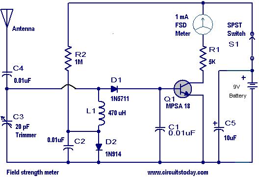
The circuit is essentially some sort of a AM receiver it self. The capacitor C3 and inductor L1 forms a tuned circuit to receive a particular frequency(the frequency of your transmitter).The diode D1 detects the signal and applies to the base of transistor Q1 (MPSA 18).The collector current of the Q1 will be proportional to the strength of this signal and will be shown in the meter M1.In result the meter reading will be a measure of the strength of the signal (of the tuned frequency) falling on the antenna.
Circuit diagram with Parts list.
Notes.
- The C3 must be varied to tune in to the frequency of your transmitter.For that,keep the antenna of meter circuit close to the antenna of your transmitter and adjust C3 to get a maximum reading on meter M1.
- Now the meter is tuned to your frequency.
- In order to tune your transmitter for a maximum range, place the meter circuit some place near to the transmitter and adjust the transmitters tuning elements.Maximum range setting will at the point where the meter shows full deflection.
- Power the circuit using a 9v battery.
- The antenna can be a 15 cm long Copper wire.
- The transistor Q1 can be any high gain NPN RF transistor.
- Switch S1 is used as a power switch.Keep this switch OFF when circuit is not in use to save battery life.Do you know Why?.If you know then please add it as a comment here.The correct answers will be rewarded.A small contest for you!.
3 Comments
sensitivity of the meter… so that the switch is made to off the circuit when not in use… and also for a short while only the circuit will work if on for several time then it will damage the circuit components…
whats the highest frequency it can detect please
Keeping the switch off will prevent current from leaking through the top power rail of the circuit. That way current is kept from leaking through the R2 network and the battery power is conserved. The capacitor is always in parrallel with the battery and will always remain charged (thus Vbattery=Vcap) and so no charge should flow there. Also there are always some AM signals floating around that the meter will pick up so a switch is necessary when not in use.