Description.
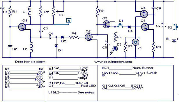
The automatic door handle alarm circuit gives a audible alarm and glows a LED when somebody touches the handle of the door.The circuit is latching type and continues to produce sound until it is switched off.
The transistor Q1 is wired as an astable multivibrator whose output is used to bias transistor Q2 to conduction.As a result the transistor q3 and LED are in OFF state.When someone touches the handle ,the capacitance of the human body damps the the oscillations of Q1.The cuts the biasing of Q2 and it goes OFF.As a result the current flows to the base of Q3 , it conducts and LED glows.If the switch S1 is ON the transistor pairs Q4&Q4 which is wired in the latching mode is triggered and the Buzzer Z1 is activated.When the person removes his hand from door handle the LED goes OFF but the buzzer continues to beep.The only way to mute the buzzer is to open the switch S2.
Circuit diagram with Parts list.
Notes.
- A9V battery or 9V DC power supply can be used to power the circuit.
- All capacitors must be rated 15V.
- To make L1 wind 25 turns of 0.4 mm enameled copper wire on resistor R2 and solder the ends of the wire to the resistor leads.This unit will stand for the R2 as well as L1 because both are parallel in the circuit .
- A readily available 10mH inductor can be used for L2 .
- Connect the point A in the circuit to the door handle using a long wire.
4 Comments
will the circuit ON even if the door handle is painted or if we connect to the painted grills
will the circuit ON even if the door handle is painted or if we connect to the painted grills?
how to switch off the sound?
this website is awesome…….