Description.
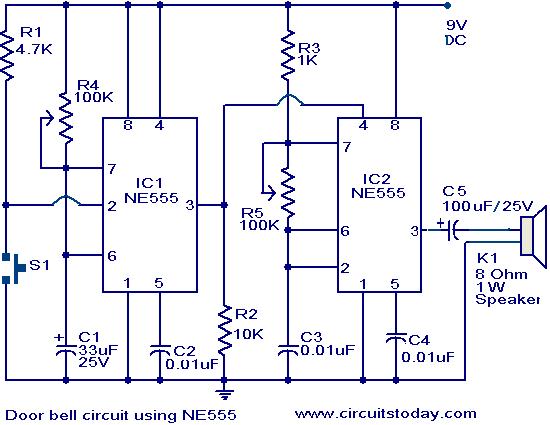
The main part of this doorbell circuit are two NE555 timer ICs.When some one presses switch S1 momentarily, the loud speaker sounds a bell tone as long as the time period of the monostable multivibrator built around IC1.
When the switch S1 pressed, IC1 is triggered at its pin 2 and output pin 3 goes high for a time period previously set by the values of POT R4 and POT R5.When the output ofIC1 goes high it resets IC2 and it starts to oscillate to make a bell sound through the speaker.The IC2 is configured as an astable multivibrator whose oscillation frequency can be varied with the help of POT R5.By adjusting the values of R4 & R5, modifications on the tone are possible.
If you are not familiar with the basics of 555 timer IC, and its applications, you can buy books that will help you get a better understanding from our online store. Totally 3 books have been reviewd in detail along with their authors. You can get their reviews and buy them here:- 3 Great Books to Learn 555 Timer Circuits and Projects
Circuit diagram with Parts list.
Notes.
- The circuit has to assembled on a good quality PCB or common board.
- The IC1 & IC2 has to be mounted on IC holders.
- Power the circuit from a 9V battery or 9V DC power supply.
- Switch S1 is push button switch.
17 Comments
Why two potR4 &R5.If only put 1 pot what’s the problem
how does ceramic can perform in whole circuit you can,t talk to those capacitor and their role in this circuit
hi thanks a lot but when I connect ground it doesn’t have sound but if I disconnect it sound
how this circuit can work in over you can’t put how it work in full in addition of those capacitor .how it work explain it i need your help very quickly please
could you please send me the full details with the procedure of connections clearly??
Works fine, I can see that the first 555 in monostable configuration with period variable (changing R4 Value) and the second 555 is Astable config in a range of audible frequencies to human ear
this circuit is good but capacitor c1 & c5 positive terminal so pls tell me c1 & c5 is use seramic ya simple capacitor….
ya c2 , c3, c4 is siramic capacitor pls ans me and resistor And capacitor work define…..
i hav made the smd version of the circuit…and its work really nice..
can u send mi the pcb circuit
sir what is the meaning of ic holders
It is an IC socket. It is for inserting the IC into the soldered socket. If you have a problem with the IC you can swap a new one without damaging the PCB by de-soldering and soldering back a new IC.
HOW TO CONNET THE CIRCUT GIVE EXPLAINTION
Hi Narayana Assemble circuit on any board. S1 is the Bell Push Switch at the door. Connect it to the circuit it will give nice sound when ever the calling bell door switch is pushed.
THIS IS NICE RELIABLE CIRCIUT.I HAVE MADE PROJECT AND ITS WORKING PROPERLY.
SO U CAN TRUST CIRCIUT DIAGRAM.
Can u please explain how to vary potentiometer to control the sound?
Can you explain what the other resistors and capacitors do?
super