The idea of home automation is not bounded to houses, the application area can be extended to security systems, auditoriums, function halls, Libraries etc. Home automation is just a catchy usage.Here, the medium for automation is not considered, only the switchboard connections are discussed. Every automation circuit finally has to control a relay through the port of the microcontroller. So, the circuit is similar up to the relay control, it slightly differs at the load terminals of the relay. Generally, NO and COM terminals of the relay are used for load control, here NC is also used.
Basic Idea
All the home automation circuits have a remote control feature, and it may be operated through Radio Frequency, Bluetooth, Infra-Red, GSM, Wi-Fi etc. But how to connect them to the existing switchboards, and what if the remote control is misplaced or if the circuit is malfunctioning? To avoid such disturbances in a practical scenario, it is better to have manual control as well similar to the switchboards.
If the relays of home automation circuits are connected in series with the existing switches, they provide semi-manual control i.e., Turn OFF is possible, but to turn ON the load, the relay has to operate. So, this is not a suitable type of connection.
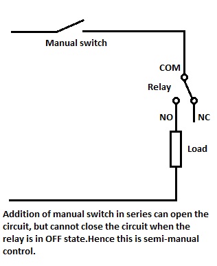
Semi-manual control
Combining Two-Way switch and relay
Two-way switches offer a solution to this. The relay is just similar to a two-way switch in terms of terminals i.e. both have three terminals like NC, COM, NO. Two-way switch connection for Staircase lighting actually gave this idea, but now, in this case, one manual switch and one electro-mechanical relay are used. Toggling any of them changes the ON/OFF state of the load.
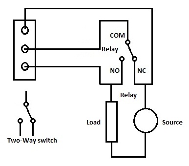 Two-Way switch and Relay combination
Actual wiring
Two-Way switch and Relay combination
By using this, existing switchboards can be modified by replacing one-way switches with two-way switches. As already mentioned, the idea of home automation is not bounded to house, the application area can be extended to security systems, auditoriums, function halls, Libraries etc. Home automation is just a catchy usage.
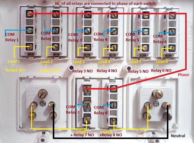
Implementation on a switch board
In the above image, Phase wire is run through all the switches on the top terminal i.e. terminal 1 and these are again connected to NC terminal of all the relays. Common terminals of switches i.e. terminal 2 of the switches are connected to the COMMON terminal of respective relays. Terminal 3 of switches are connected to loads and again connected to NO terminal of relays.
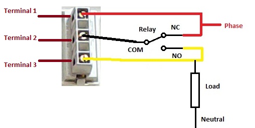
So, while modifying the existing one-way switchboard, the common phase is connected to terminal 1 of two-way switches and loads are connected to terminal 3 of two-way switches. In addition to this, three terminals of switches are connected to three terminals of relays as,
Two-way switchRelay
Terminal 1 ——- NC
Terminal 2 –—– COM
Terminal 3 ——- NO
Now, the loads can be turned ON/OFF manually through switchboard as well as remotely. Suppose if manual operation is not used, then turn OFF all the switches, now this state is similar to One-way switchboard with all the switches in OFF state. All the loads can be operated remotely. Their status can be known from the remote device itself. Suppose, if automation circuit fails i.e., relays in OFF state, then loads can be operated manually similar to One-way switchboard.
While using manual along with automated operation, in order to get the status of the loads, an additional circuit is required to read the ON/OFF state of the loads. This is generally required if the user is at a remote location like for a house, if the operator is at the office or on a journey, reading the load status is required. But it is not essential, when the user/operator is in sight of the loads, for example, ON/OFF status of the load is directly visible.
Relay board can be placed below the switchboard in a separate enclosure along with the automation circuit. However, in typical situations and requirements, an opto-coupler based sensing circuit can be included in the circuit, if the status of loads is required.
Comments are closed.