Description.
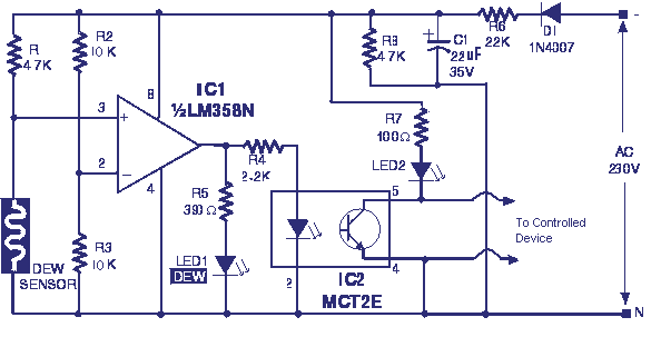
Here is a simple circuit that can be used to switch ON or OFF a device when the dew present in the surrounding atmosphere crosses a set value. The circuit uses a dew sensitive resistive element and a comparator based on LM 358 to perform the above said operation.
At normal condition the resistance of dew sensor element will be low and so the voltage drop across it. So the voltage at the non inverting pin of LM358 (IC1) will be less than the voltage at the inverting input of the LM358. So the output of the opamp will be low. This keeps the opto-coupler (MCT2E) deactivated.When the dew increases the resistance of the element increases and so do the voltage across it.Now the voltage at the non inverting pin of LM358 (IC1) will be higher than the voltage at the inverting input of the LM358. So the output of the op amp will be switched to high. This in turn activates the optocoupler. The LED glows to indicate it. As a result we get an optopcoupler activated and de activated according to the amount of dew in the atmosphere. The output pins of optocoupler pin (5&4) can be used to control the external device.
Diode D1, resistors R6 & R3 and capacitor C1 is employed here to derive the power for the circuit directly from mains.
Circuit diagram with Parts list.
Notes.
- The dew sensor is hard to find in market.But it can be easily obtained from a old VCR. Also the type no of the sensor is not so important here. Try with any thing you get. I used one from a old Hitachi VCR.
- LM 358 is a dual opamp. Here only one opamp inside it is used.
Story behind this circuit.
One day (when I was in high school) I was doing autopsy on our dead old VCR. Some way I found a component that was not familiar to me. I asked a TV mechanic about this. He said, that was a dew sensor. Suddenly the idea clicked in my mind. Why couldn’t I make a dew sensitive switch using this sensor. The result was great. Actually in my first prototype there was no opamp or opto-coupler and had only two transistors. One tuned to sense the voltage change across sensor and other to drive a relay. The circuit shown here is a modification later done by me.


11 Comments
ICI 1/2LM358N is not labelled can you please explain me bcoz i am current doing this as project at polytechnic
Hi Nik You are right. the opto-coupler should be used a phanthom supply so that the real galvonic isolation can be achieved. MCT2E pin 4&5 should be energised by the remote supply for any remote monitoring
Hi ! IMHO, this circuit is *very dangerous* because it shares power rails with the mains supply. And the circuit is un-fused. A mains spike could ride right down into the electronics, blow across the dropper resistors and *bite* you. Due care, please ??
Hi I have a real doubt in the operation of the circuit. R6 can allow a maximum of 20mA current. with IC out put at low, with no LEDs glowing the supply voltage for the IC will raise to >90volt. So a Zener diode of 12 volt to be added in parallel to C1. with 12volt supply MCT2N will get 5mA LED current during switch on(at dew formation) which is just sufficient to operate it(less than 12Volt dc will produce very low current which is not sufficient for MCT2N to operate) . But with 12volt DC supply LED1 will consume 26mA and LED2 will consume 100mA?(R6 will supply only 20mA) author may kindly explain the operation.
I like this circuit,(DEW SENSITIVE SWITCH) can you tell me how much wattage will I know for every resistor used in the circuit? thanks a lot. and more power..
hahahahahahahahahaahha
do you have the code for this switch
do you the code for this switch
Where may I buy Dew sensitive switches as posted at CircuitsToday?
I find myself little bit difficult to use this switch. As far as I understand this device can be used to sense the dew, but where