Current amplifier and buffers.
Buffer amplifier.
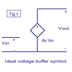
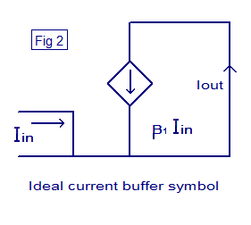
Buffer amplifier is a circuit which transforms electrical impedance from one circuit to another. The main purpose of a buffer is to prevent the loading of a preceding circuit by the succeeding one. For example, a sensor may have the capability to produce a voltage or current corresponding to a particular physical quantity it sense but it may not have the power to drive circuitry it is connected to. In such situations a buffer can be used. A buffer when connected between the sensor and the succeeding circuitry easily drives the circuitry in terms of current or voltage according to the sensor output.Buffers are classified into voltage buffers and current buffers. The symbols of ideal voltage buffer and current buffer are shown in Fig 1 and Fig 2 respectively.
 |
 |
Voltage buffer.
A circuit which transfers a voltage from a circuit with high output impedance to a circuit with low input impedance is call a voltage buffer. The voltage buffer connected between these two circuit prevents the low input impedance circuit ( second one) from loading the first one. Infinite input impedance, zero output impedance, absolute linearity, high speed etc are the features on an ideal voltage buffer.
If the voltage is transferred from the first circuit to the second circuit without any change in amplitude, then such a circuit is called unity gain voltage buffer or voltage follower. The output voltage just tracks or follows the input voltage. The voltage gain of the voltage follower is unity (Av = 1). Even though there is no voltage gain, there will be a sufficient amount of gain in current. So when a voltage follower is connected between two circuit, it will transfer the voltage from first one to second one without any change in amplitude and drives the second circuit without loading the first circuit.
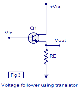
A voltage buffer can be realized using opamp, BJT or MOSFET. Voltage follower using transistor (BJT) is shown in Fig 3. Voltage follower using BJT is also known as emitter follower. +Vcc is the transistor’s collector voltage, Vin is the input voltage, Vout is the output voltage and Re is the transistors emitter resistor.
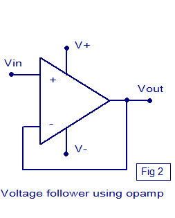
Voltage follower implemented using opamp is shown in Fig 2. This is done by applying full series negative feedback to the opamp ie; by connecting the output pin to the inverting input pin. Here the opamp is configured in non inverting mode (refer Figure 2). So the equation for gain is Av= 1 + (Rf/R1).
Since output and inverting input are shorted ,Rf=0 .
Since there is no R1 to ground, it can be considered as an open circuit and so R1 = ∞
There fore (Rf/R1) = (0/∞) = 0.
Therefore Voltage gain Av = 1 + (Rf/R1) = 1+0 =1.
 |
 |
Current buffer.
Current buffer is a circuit that is used to transfer current from a low input impedance circuit to a circuit having high input impedance. The current buffer circuit connected in between the two circuits prevents the second circuit from loading the first circuit. The features of an ideal current buffer are infinite input impedance, zero output impedance, high linearity and fast response. A current buffer with unity gain (B=1) is called a unity gain current buffer or current follower. Here the output current just tracks or follows the input current. A current buffer can be realised using transistor (BJT or MOSFET).
Current amplifier circuit.
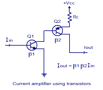
A current amplifier circuit is a circuit which amplifies the input current by a fixed factor and feeds it to the succeeding circuit. A current amplifier is somewhat similar to a voltage buffer but the difference is that an ideal voltage buffer will try to deliver whatever current required by the load while keeping the input and output voltages same, where a current amplifier supplies the succeeding stage with a current that is a fixed multiple of the input current. A current amplifier can be realized using transistors.The schematic of a current amplifier circuit using transistors is shown in the figure below. Two transistors are used in this circuit. β1 and β2 are the current gains of transistors Q1 and Q2 respectively. Iin is the input current, Iout is the output current and+Vcc is the transistor T2’s collector voltage The equation for the output current is Iout = β1 β2 Iin .

16 Comments
“ideal current buffer are …high linearity and fast response”
i suggest:
“perfect linearity and instantaneous response”
“The features of an ideal current buffer are infinite input impedance, zero output impedance, high linearity and fast response.”
Look at your own diagram. the input impedance is zero = a short circuit. The output impedance is infinite, an ideal current source. You’ve got it backwards.
Hi,
“Even though there is no voltage gain, there will be a sufficient amount of gain in current”
Could you please tell me why there will be a current gain in the voltage buffer?
Ohm’s Law states that Voltage = Current * Impedance.
A buffer amplifier (or voltage follower) is a circuit designed to only replicate the input voltage, not the current. So, based on Ohm’s Law, when voltage is fixed, current is effected. The amount of current gain is set by the device connected to the amplifier output. A low impedance will demand lots of current and create a larger gain; vice-versa for a high impedance. Thus the amplification. Now for why amplification is needed.
Device 1 has an output of 5V @ 20mA. This device will connect device 2, but there is a problem. Device 2 requires 5V @ 50mA to operate properly. Uh-oh. Now I have a problem. But wait!!!! I just remembered about Buffer Amplifiers!! They can amplify current!! So i build one, and I put it between device 1 and device 2. Now I can use device 1 and device 2 together, with full functionality, and I don’t have to worry about malfunctions from either of them.
Bad signal chain: Device 1 —> Device 2 Problem: Device one does not supply enough power.
Good signal chain: Device 1 —> Buffer —> Device 2 Solution: Buffer amplifies current to increase power.
One other note: Yes, to increase power you can amplify current OR voltage, however, there are a lot of situations that require a specific voltage. Deviating from that voltage can be harmful to the device. That is when Buffer Amplifiers come in handy.
A Voltage Buffer doesn’t sound like much more than a good way of transferring a cv signal- if current is effected I’m not sure that it would be much more than filling two conjoined pipes with water- it might only amplify current to approximately equal with the previous current- create a greater current drop along mainline to balance the circuits… but I’d have to research the reason that amplifiers work anyway… because I’m not sure why they work at all.
Can someone pleas help me with a simple working circuit diagram of a current amplifier
I am not able to the understand what you meant by the following line:
“Buffer amplifier is a circuit which transforms electrical impedance from one circuit to another”.
Basic concept which i perceive is that the buffer tries to optimize the current or voltage required by the 2nd circuit according to the 1st one(for this case).
From where Impedance comes in picture?
Hi Thomas the buffers are meant for the source to avoid getting loaded heavily by the the load. (such that the source will not be disturbed by different value loads). If you are designing the whole circuit you can take care of the load requirements, but if you are going to use standard assembled modules available to match your circuits the buffers are a must.
I am unclear regarding buffer. Is buffer kind of circuit connect between two circuits to lower or up the value of current or voltage in order the second circuit work properly according to its own current or voltage value. My question is, why we need buffer, can we design first circuit correspond the voltage or current values of second circuit. If I am not clear, would you please provide other example beside sensor to clarify the function of buffer. thanks.
Buffer is constant Voltage, changing current.
“My question is, why we need buffer, can we design first circuit correspond the voltage or current values of second circuit.”
I bought 2 devices. Each one was designed by someone different, but they need to work together perfectly, and they must operate at 5V. Device 1 has an output of 20mA. This device will connect device 2, but there is a problem. Device 2 requires 50mA to operate properly. So i build a buffer circuit between device 1 and device 2. Now I can use device 1 and device 2 together, and they will work fine.
Bad signal chain: Device 1 —> Device 2
Problem: Device one does not supply enough power.
Good signal chain: Device 1 —> Buffer —> Device 2
Solution: Buffer amplifies current to increase power.
About the current amplifier…You should connect a resistor to the base of B1 transistor.