Description.
The contact less telephone ringer circuit can produce a ring as well as a visual indication when a call comes.The main advantage is that since there is no direct contact between the phone line and the circuit there is no chance for a loading or disturbance in the telephone line.
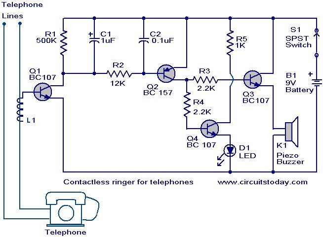
When the telephone rings 60 Hz AC signal is generated which produces a proportional magnetic field around the telephone lines.These magnetic field will be picked up by the coil L1 due to electromagnetic induction.A proportional voltage is developed across L1 and it will bias transistor Q1 to ON.This results in the conduction of transistors Q2,Q3 andQ4.The buzzer will ring and the LED will glow.The switch S1 acts as an ON/OFF switch.
Circuit diagram with Parts List.
Notes.
- For L1 make 50 close turns of 28 SWG enameled copper wire on any of the two telephone wires.Connect one end of the coil to base of Q1 and leave other end free.
- If the circuit not works by try by changing the end of the L1 connected to base of Q1.
- A 9V transistor radio battery can be used as the power source.
- Assemble the circuit on a good quality PCB or common board.
- Use of this type or any other devices other than the allowed telephones and devices with the telephone line may be a law violation in some nations.Check it properly before trying.
7 Comments
hi sir, i found your diagram very usefull…bt can we found a similar diagram for cellular phone or gsm phone? thank you
FYI, ringer freq is 20 HZ in U.S. except for some smaller companies that use 30 HZ, also if any still exist 4 party lines use 20,30,40,50 HZ
FYI, in the US anyway, the ringing freq. is 20 cps NOT 60 cps.
Thanx good information………
………
.
thanx
without any conection of L1 to telephone line the buzzer and led are still buzzing and glowing respectively.
what is the problem kindly guide me as soon as possible