In this tutorial, we are building an interesting application using Arduino and PIR Sensor. A Burglar Alarm – is basically an intruder alarm or an anti theft alarm. So this project is all about building an anti theft alarm or an intruder alarm using Arduino and PIR sensor. It is possible to enhance this project with many features like adding a GSM module to send SMS alerts to specified mobile numbers when an intruder is detected (when a motion is detected inside the range of PIR sensor). So lets get to building our burglar alarm project using arduino.
Lets first build a simple diy burglar alarm using Arduino, PIR sensor and a buzzer only. If you are a beginner, you need to read the following tutorials to build this circuit perfectly.
1. What is Arduino – read this article if you are very new to Arduino.
2. Blink LED with Arduino – say Hello World! – Learn how to blink leds using Arduino!
3. Simple LED Projects using Arduino – Get your hands in it! Do some LED projects using Arduino to get the basics!
4. Interface PIR Sensor to Arduino – Learn about how a PIR sensor works and how it is interfaced to Arduino.
Go through above tutorials before you try building this burglar alarm system using arduino! So lets begin our project.
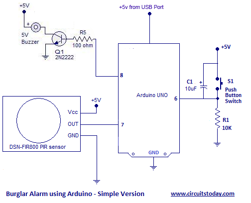
The circuit diagram to build a simple burglar alarm or an intruder alarm using arduino is given below. You may assemble the circuit as shown in the diagram. Before getting into working of the alarm circuit, I shall brief the components used in this project.
PIR Sensor – is the heart of this simple burglar alarm circuit using arduino. A PIR sensor – is basically a motion sensor or a motion detector which identifies any object that moves inside its range of view. PIR sensor identifies infra red radiations emitted by any object under its radar range.
Buzzer – is used to create a sound alarm when ever a movement is identified inside the range of PIR sensor. A transistor 2N2222 is used to drive the buzzer. The maximum current that can be sourced or sinked from an arduino pin is 20mA (the total current being 200mA from different pins). But the buzzer will need more than just 20mA for its proper functioning. So how to give the necessary current required fir buzzer ? We use switching transistor 2N222 for this purpose. It can act as a switch and at the same time it provides the required current amplification. A 2N2222 transistor with a gain of 100 can give upto 1A current at its output. Another purpose of using a transistor in between arduino pin and buzzer is isolation. A short circuit of the buzzer will destroy only the collector – emitter junction of transistor. Since their is isolation at the base region of transistor (base is connected to arduino), the destruction of collector-emitter junction will not affect base and hence our arduino will be safe from getting burned! The 100 ohms resistor at base is used to limit base current of transistor.
Switch – a push button switch is used to reset the burglar alarm once its activated. The capacitor is used for bypassing bouncing effects of a switch ( debouncing capacitor).
Burglar Alarm using Arduino – Circuit Diagram
Connections Explained
Arduino – Pin 7 – Output of PIR Sensor | Pin 6 – Push button switch | Pin 8 – Buzzer
Buzzer – + pin to Vcc (5 volts) | other pin to collector side of 2N2222
Transistor – 2N2222 – NPN – Collector to Buzzer | Emitter to Ground | Base to Arduino through 100 Ohm Resistor
Switch – One end of switch to +5V | Other end to Ground through a 10K current limiting resistor
PIR Sensor – has got 3 pins – Vcc to +5 volts | GND to Ground | OUT pin to Arduino pin 7
Note:- Wire all grounds together at a common point.
The Program
int sensor=7; //The output of PIR sensor connected to pin 7
int push_switch=6; // push button switch connected to pin 6
int buzzer=8; // buzzer connected at pin 8
int sensor_value; //variable to hold read sensor value
void setup()
{
pinMode(sensor,INPUT); // configuring pin 7 as Input
pinMode(push_switch,INPUT); // configuring pin 6 as Input
pinMode(buzzer,OUTPUT); // configuring pin 8 as OUTPUT
}
void loop()
{
sensor_value=digitalRead(sensor); // Reading sensor value from pin 7
if(sensor_value==HIGH) // Checking if PIR sensor sends a HIGH signal to Arduino
{
  digitalWrite(buzzer,HIGH); // Activating the buzzer
}
if(digitalRead(push_switch==HIGH))// Checking if pushbutton was pressed
{
digitalWrite(buzzer,LOW); // turning OFF the buzzer
}}
So we have finished our simple diy arduino burglar alarm. How easy was that? Try installing this diy intruder alarm in your garden area and see its practical application.
Advanced version of the Project – SMS Burglar Alarm using Arduino with GSM Module
Since we have built a simple arduino anti theft alarm, why not build an advanced version of the same burglar detector? What if we can build a burglar alarm that texts you an sms when an intruder is detected ? cool idea – isn’t it? So lets get our hands at it – a burglar alarm that sends text message (sms) using arduino and pir sensor.
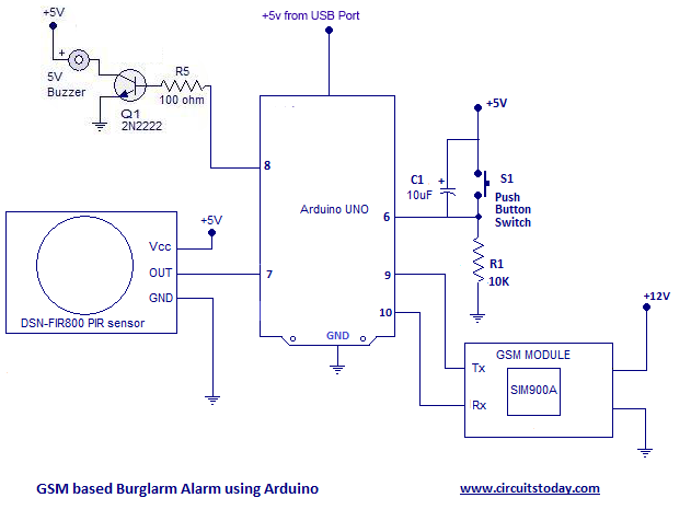
We are going to use a gsm module in addition to components and modules used in above circuit. You need to have an idea of how to interface a gsm module and arduino together before you begin this project. Assemble the circuit as shown in the gsm burglar alarm circuit.
GSM/GPRS Module – Buyers Guide – you don’t own a GSM/GPRS module? are you looking to buy one? Please go through our detailed buyers guide for GSM/GPRS module which helps you to choose the right module in the right price range.
GSM based Arduino Intruder Alarm – Circuit Diagram
Connections Explained!
Refer previous circuit diagram and its explanation first. The only addition module used is GSM Module.
GSM Module – Connect its Tx pin to Pin 9 of Arduino | Connect Rx to Pin 10 – Arduino | Vcc or Power Jack to +12 Volt | Make GND or Ground pin common to all other components and modules
Objectives of the PIR Sensor Alarm using Arduino
- Detect a motion – an intruder or a burglar using PIR sensor
- Activate the buzzer alarm upon detection of burglar/intruder – Alarm should sound until Reset switch is pressed
- Send 3 SMS to a predefined mobile number set inside the program.
- Stop the alarm when reset switch is pressed. Also reactivate the SMS alert facility upon reset.
The Program
#include<SoftwareSerial.h>
SoftwareSerial mySerial(9, 10);
int sensor=7; //The output of PIR sensor connected to pin 7
int push_switch=6; // push button switch connected to pin 6
int buzzer=8; // buzzer connected at pin 8
int sensor_value; //variable to hold read sensor value
int sms_count=0;
void setup()
{
pinMode(sensor,INPUT); // configuring pin 7 as Input
pinMode(push_switch,INPUT); // configuring pin 6 as Input
pinMode(buzzer,OUTPUT); // configuring pin 8 as OUTPUT
mySerial.begin(9600);
}

void loop()
{
Check_Burglar();// subroutine to check sensor status and activation of outputs
Check_Reset(); // subroutine to check if alarm reset switch pressed or not
}

void Check_Burglar()
{
sensor_value=digitalRead(sensor); // Reading sensor value from pin 7
if(sensor_value==HIGH) // Checking if PIR sensor sends a HIGH signal to Arduino
{
  digitalWrite(buzzer,HIGH); // Activating the buzzer
  while(sms_count<3) //Number of SMS Alerts to be sent limited at 3
    {
      SendTextMessage(); // Function to send AT Commands to GSM module
    }
}}

void Check_Reset()
{
if(digitalRead(push_switch==HIGH))// Checking if pushbutton was pressed
{
digitalWrite(buzzer,LOW); // turning OFF the buzzer
sms_count=0; // Reactivating the SMS Alert Facility
}}

void SendTextMessage()
{
  mySerial.println("AT+CMGF=1");    //To send SMS in Text Mode
  delay(1000);
  mySerial.println("AT+CMGS=\"+919495xxxxxx\"\r"); // change to the phone number you using
  delay(1000);
  mySerial.println("Gas Leaking!");//the content of the message
  delay(200);
  mySerial.println((char)26);//the stopping character
  delay(1000);
  sms_count++;
}
So how simple was that advanced arduino intrusion alarm using GSM module ? The program is self explanatory! If you have any doubts, please ask in comments section.
52 Comments
hi
I want built a burglar alarm that can send sms and call by using pir sensor,sim800l and arduino uno . is there anyone to help me?
if u have its cod and learning please send to my email (hassansedaqat66@gmail.com)
Circuit not working please. I tried connecting as explained but the buzzer won’t come on. PIR not detecting motion I guess. Switch key having no effect on the circuit.
I cannot get the text messages sent to my phone. Not sure where the problem might be. My GSM shield shows connection is made, the sensor notes movement, the output is triggered, but no SMS. Please give me some suggestion sir.
I built this project awesome .but I have notice it send massage after 1 hour repeat massage next hour . any buddy have suggested what’s where wrong .? False trigger how avoid
I built this project but I m notice arduino send message after 1 hour reputedly any body have solution what’s the problem are
hi
I want built a burglar alarm that can send sms and call by using pir sensor,sim800l and arduino uno can u help me ? if u have its cod and learning please send to my email (hassansedaqat66@gmail.com)
Dear All,
When I Press S1 not found any respnose
Hello Sir
Thanks for the awesome project it was much easier to understand with your comments on every line of code.
Can you help me out in bringing a little change in same project, What I want is a user can enter/change his mobile number by simply sending a SMS to the SIM in gsm module.
Buzzer immediately turns on when I power the arduino board and remains on all through… What I’m I missing?
I tried implementating the Burglar Alarm using Arduino circuit but the buzzer remains constantly On. I tested the separate units of the circuit; using the switch and PIR to turn on the buzzer and it works fine. But interfacing it with my arduino Uno I still get the same result. Buzzers remains constantly On but when the PIR is activated, the buzzer becomes more louder. What could I be missing
This is really a very nice project. But I am facing a problem. The gsm modem is not sending any sms after working perfectly twice. Thougb I have not changed the code or anything.
Kindly help me to fix the problem.
Thank you!
This is really a very nice project. But I am facing a problem. The gsm modem is not sending any sms after working perfectly twice. Thougb I have not changed the code or anything.
Kindly help me to fix the problem.
Thank you!
Unfortunately my buzzer immediately turn on after powering my arduino board and stays ON. Though the buzzer sound becomes louder after the Pir goes HIGH. I have tried to verify the circuit connections again and its still the same thing. What I’m I missing?
And suppose i install this protype on more than one place, then how one knows the message is from that specific location?
If any body tempered the PIR sensor and/or the connections(connection wires) before theft, then what will be the response of this prototype??
Please guide!
Bro can we use 5v battery to power arduino
i am using sim900 with arduino uno and i want to interface a radar sensor hb100 to read the speed values and send through gsm but whole process should be done without manual interference means after damping code the circuit should work with out system and should work with a battery .so plz someone suggest me the code to implement this.
Hello,
Could you please direct me to where buy these modules ?
and:
1. how do is top the alarm with a sms text instead of pressing the switch(incase if unable to get to the device)
2. what other codes i can send to the device via sms (controlling it etc)
3. can you hi-light in the Arduino code where the parts I can edit with my own details ? txt msg words etc ?
thanks
sir, pin 9 and 10 of arduino are different while i think the RX and TX of gsm module should be connected with RX TX of arduino that is pin 0 and 1.
The alarm doesn’t turn off when push button is pressed.. Hlp
Really appreciate ur wrk.. But wen I press push button, the alarm doesn’t stop.. Plz hlp
Pls Help Me Its Not Sending SMS On my phone number
Dear friends,
PLZ help me I can’t complet my project becouse when i join all the item acording to the circuit digram but when I add my SIM800 gsm module the buzzer always goes on with out any reason and sms alart goes on my cellphone without any reason.What should i do.
What type of Arduino ? Is it ATMEGA328 ?
Best GSM module guidance sketch with details explained. I am developing laser security alarm with PIR sensor as well. Succeeded in testing it.
Thanks a lot. Your free guidance will be used by all in a long way to go. Thanks a lot Sir/Madam.
sir which software we require while dumping program?
im using sim 800l gsm pls give me a code of this.
this is a very nice project.. how to add alarm off/on via sms…. please help me..tq
I cannot get the text messages sent to my phone. Not sure where the problem might be. My GSM shield shows connection is made, the sensor notes movement, the output is triggered, but no SMS. Any suggestions? Thanks for any ideas.
Hello sir, is there a need of load in gsm module to send an sms ?
@Sherylle – Wire the circuit as shown in diagram. Make sure your code is correct.
It is obvious. U have to include GSM Module.
how the coding if I want to send it to another phone number at the same time. (+6012960xxxx, +6019929xxxx, +6011234xxxx)
mySerial.println(“AT+CMGF=1”); //To send SMS in Text Mode
delay(1000);
mySerial.println(“AT+CMGS=\”+919495xxxxxx\”\r”); // change to the phone number you using
delay(1000);
good day Sir,
If I want to produce ring in my mobile instead of SMS alert , what part of the code to be changed,
please advice,
raegards
Uttam
You have to edit the subroutine SendTextMessage()
can you show the full code to produce ring?
Sir,
I have SIM300, will it work with this arrangement or what changes to be made with program to make it work , Please guide,
Apart from SMS how to get contenious ring , what changes to be made with program to get this,
Please guide
ATCommands are same for SIM300 and SIM900 – for sending message. To ring, use ATcommand for calling – ADT
We need more ingihsts like this in this thread.
I have connected according to your instruction. But it is sending SMS continuously. The push button is not stopping the buzzer or gsm module. Can you please help me?
The following statement has a bad error.
if( digitalRead(push_switch == HIGH) ) // Checking if pushbutton was pressed
Sir I’m making this project but my GSM Module is not connected to network,, how to resolve this problem?? kindly guide me please… I’m using SIM900A Module.
good day sir,
In the GSM based Arduino Intruder Alarm – Circuit Diagram there are 2 different voltage source 5v and 12 v. Can i make the PIR, Arduino UNO, Switch and Buzzer in parallel connection to the 5volts same source (what type of battery). And for the GSM module what type of battery and ampere rating? I would like to make an alarm for my motorcycle. i hope i can put the whole module inside the toolbox of the motorcycle.
@Rey John, You can use a general purpose USB battery pack like this – http://amzn.to/1pniOu6
Basically, Arduino, GSM Module and PIR sensor are low power devices. They dont need much current (than a few mA) for their proper functioning. And about the difference in power supplies, you can always buy a GSM module that operates on +5v source. Buy a GSM module that can be powered from a +5v source – like this one – http://amzn.to/1Qqfg0Q
hi sir. i was trying to change the pir sensor with a piezo disc and and i also want to deactivate the buzzer by pressing the button or sending sms in the gsm…
i’m having trouble with the program on how to deactivate the buzzer if i replied to the sms send to my phone…. thanks your sir.
here after ringing buzzer I will switch on s1. Then in next loop checking, my s1 will be in on position still ,then in this loop what happens to buzzer output
@Mouli – You are supposed to use a Push Button Switch. A push button switch generates a High pulse only for the time the switch is kept pressed. Once you release the switch, the switch will go open and the pulse from switch will be back to LOW. I think, you are mentioning about a “Push to ON” switch. The program is written for the push button switch (just like the reset switch of 8051).
good day everyone!!. i am currently working on a project with arduino uno using pir sensor and push button. this is how the module should work, first , pir sensor will detect presence of human and light up the led( i substitute the buzzer with led), after a moment if the button is pushed, the led will turn off and waiting for the input form pir sensor again . it seem does work as i expected. really need your help as i am very new with arduino.. here the code.
int sensor=7; //The output of PIR sensor connected to pin 7
int push_switch=6; // push button switch connected to pin 6
int led=8;
int sensor_value; //variable to hold read sensor value
void setup()
{
pinMode(sensor,INPUT); // configuring pin 7 as Input
pinMode(push_switch,INPUT); // configuring pin 6 as Input
pinMode(led,OUTPUT);
}
void loop()
{
sensor_value=digitalRead(sensor); // Reading sensor value from pin 7
if(sensor_value==HIGH) // Checking if PIR sensor sends a HIGH signal to Arduino
{
digitalWrite(led,HIGH); // Activating the buzzer
}
if(digitalRead(push_switch==HIGH))// Checking if pushbutton was pressed
{
digitalWrite(led,LOW); // turning OFF the buzzer
}
}
Dear sir,
In the GSM module there will be one SIM and in the subroutine ( send Text Message)there are two mobile numbers used, Is that first one the SIM card Number of the GSM Module and the second one the Mobile number where the SMS has to be send!!!!
Kindly clarify please.
S.yogaraja.
@Yogaraja – They are two different mobile numbers and SMS will be sent to both of these numbers. It is not the number of SIM card inside GSM module. Hope you understood!
@Yogaraja – I have edited the code! Now its code to send SMS to one mobile number only.
i m facing problem it is not sending sms on my phone pls help me