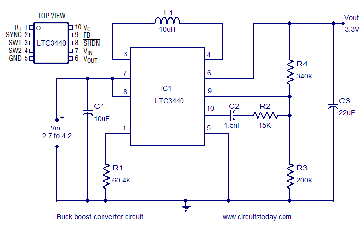
Buck Boost converter circuit using LTC3440
Description.
A very efficient buck boost converter circuit is shown here. The circuit is based on the LTC3440 buck boost regulator IC from Linear Technology. The LTC3440 requires only one inductor and provides up to 96% efficiency. There is no need of Schottky diode for applications where output voltage is less than 4.3V and the IC can deliver up to 600mA output current.
In the circuit the IC is wired as a buck boost regulator providing 3.3V output from a 2.7 to 4.2V input. R1 is the timing resistor which determines the oscillator frequency and it can be varied between 300 KHz to 2MHz by varying the value of R1. C1 is the input bypass capacitor for reducing noise and C3 is the output filter capacitor. Resistors R4, R4 sets the output voltage and the network consisting of C2 and R2 is meant for frequency compensation.
Buck Boost Converter Circuit diagram.

Notes.
- Assemble the circuit on a good quality PCB.
- Input voltage can be between 2.7 to 4.2V.
- L1 can be a toroid, potcore or shielded bobbin inductor.
- C1 to C3 are ceramic capacitors.
Following circuits may be also useful to you:
5V buck regulator using LM2678
Switching Regulator using LM1758 A
6 to 12 Voltage converter using TDA2003

9 Comments
what is the voltage rating and current rating of the capacitors and inductor of this buck-boost converter circuit?
plz help me.
i hv have to submit this project a day after tommor.
so plz help me.
plzzzzz
Hi all capacitors are to be rated for 6 volts or higher. the torroidal inductor is rated for 1 amp. All resistances are 1/4 watt 1% metal film .
I checked the motor- it is giving around 500mA- would the MAX641 based circuit work? would it be able to give enough current?
Hi Philip please check what is the maximum current you can get from your generator. you require around 300 to 400mA at 6volts for charging the mobile phones, though the battery is rated for 3.7 volts, as it containes protection circuit etc.
Hi what i have in mind is a mobile charger which we can power using a fan turned into windmill. i use a dc motor to generate power but the max voltage is only about 2.5V. can we use the circuit in the link you provided for this purpose? The battery is a 3.7 V 1020mAh battery. The normal wall socket charger gives 6V output.
hey u can mail it to me.
hey seetharaman plz help me with the design of battery charger using scr,my battery is of 12v,1.3AH..and can u plz tell me the wattages of other resistors used.plz reply fast.
Hi Philip Joy you may try MAX641. use the following link.
http://www.elektropage.com/default.asp?tid=751
The IC is not available- can u suggest another circuit which can convert a similar variable voltage (~1-5V) to a constant voltage- say 5 or 6 volts?