DIY-Bluetooth based Home Automation Project
In this project, let’s see how to design a Bluetooth based home automation project.This article explains the steps involved in the designing of a Bluetooth home automation kit, starting from the configuration of a Bluetooth module. The article also explains how to select an App, read the keywords sent by the App and how to develop a microcontroller program compatible with the selected App. Program file and Program code are provided, which can be readily used. By the end of the article, a complete ready to use Home automation kit is developed.
Program file (hex file) and Program code are provided, which can be readily used after downloading. Finishing this tutorial, you should be able to design and develop a complete bluetooth based home automation kit.
Selection of the Android App:
Android Apps are readily available in Play Store for home automation using Bluetooth module. We have to select an App that suits our requirement. The number of loads or appliances that are controlled by the app is the basic criteria for app selection. This number should match with the actual number of relays/loads in our Automation Hardware kit. In this article, we are using an 8-Channel Relay board i.e., it can control 8 Loads or devices (like fan, light etc). So, we need to select an App that can control 8 Loads. Apps for Bluetooth control are available in Playstore You can download any one you like.
Keywords from the Android App:
The reader will be able to develop the microcontroller program for any App by knowing the commands used by the App to control devices. The Android App sends specific characters to ON/OFF a particular load. These characters can be single alphabets, numbers, special characters or words. This is decided by the App Designer/Programmer. These specific characters are referred as Keywords in this article.
The App developer may or may not provide the Keywords in the description of the App. In order to use the App, it is essential to know these Keywords. One of the simple methods to find the keywords is presented here.
The idea is to interface the module with the hyper terminal software using a USB-Serial converter. The procedure below explains how to use the hyper terminal software and send the commands using the USB-Serial converter. Please read our article on Interfacing Bluetooth modules for a detailed explanation.
Keywords from the Smartphone
Configuring the Bluetooth module:
By using the hyper terminal software, the data received by the Bluetooth module can be read. For this purpose, the Bluetooth module should be configured as a slave that accepts connection with any device. The series of commands is shown below. Connect the module with the USB-Serial converter as shown below.
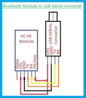
Power ON the module with USB cable and Press the Key/EN switch if the key switch is provided in the module or Input HIGH to PIN 34 of the module. This is different for different modules. After entering into AT Command mode, send the following commands.
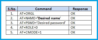
The above commands will configure the module to the slave role and the module will get connected to any device like the smartphones. This configuration is sufficient for our home automation circuit as well.
This module is now ready to receive the data from a smartphone. By operating the load switches in the App, the Bluetooth module inside the phone will send respective keywords for the loads. These keywords are visible in the Received Text box of the hyper terminal software. Make a note of the keywords of all the loads. Now, we will develop a microcontroller program to operate the relays according to the data received.
Now, let’s develop a microcontroller program to operate the relays according to the data received.
Configuration of Bluetooth module
Developing the Microcontroller Program:
Any microcontroller with the UART, TIMER features, nd 8-I/O pins is suitable for this circuit. 8 I/O pins are used as outputs to control 8 relays. In this article, ATMEGA 32, a microcontroller from AVR family is used. The size of our program code i.e., the HEX file size is about 3 KB. So, the microcontroller ATMEGA 8 is also sufficient.
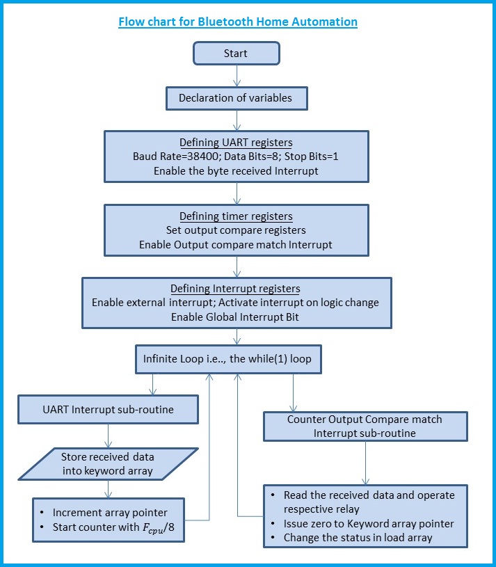
The data received by the UART Peripheral is read, and the corresponding relay is operated. For this purpose, UART data received interrupt is enabled. The bit name is RXCIE–Receive Complete Interrupt Enable. Whenever a byte is received from the Bluetooth module an interrupt is generated. Timer/counter is initiated at this instant. For a preset time the timer operates and when the counter value reaches the value set in the Output Compare Registers, an interrupt is generated. The compare match Interrupt sub-routine will read the byte and executes the relay switching function. Thus, the corresponding relay is operated.
The timer is involved because, if the keywords are of multiple characters or words other than single alphabets, we have to wait for the entire word to be received and then we have to read the word. So, when a word is received, the delay between one byte to the next byte will be very less. After completion of the word, the delay will be more and hence the timer interrupt is activated. The program flow chart is shown below.
Program/Code – Bluetooth Home Automation
The program is given below as a downloadable link (a zip file). The file contains program in C language and also the Hex file to burn directly on to your Atmega micro controller.
Download Program – C File and Hex File (Zip)
The C language program is compiled using the software ‘MikroC Pro for AVR’.
The project building procedure using the ‘MikroC pro for AVR’ software is shown below.
The trial version software is enough to build programs up to a code size of 8 KB.
Building the code in Programming Software
Relay Board connections:
In this circuit, an 8-Channel relay board is used. In this relay board, every relay has 3-Terminals on the load side. So, it is an SPDT switch-Single Pole Double Throw Switch. In general, the terminals NO and COM are used to make or break the circuit. However, if the automation circuit should be combined with the manual switchboard, two-way switches should be used in the switch board and the terminals NO, COM, NC of the relay should be connected to each terminal of the manual 2-Way switch. For a detailed explanation, please go through our article on ‘Home Automation Switch Boards’.
The coils of the relays are powered by a Driver IC ‘ULN 2803’. This avoids the use of transistors and its base resistors, thereby reducing the PCB size. The SMPS can be powered with the incoming Phase and Neutral into the switchboard.

Take precautionary measures while connecting the kit to the loads. Please Turn OFF the Mains before making connections. It is better to take the help of an electrician for the beginners.
Real-Time Usage:
While configuring the module, set a name to the module, such that while searching for the devices in your smartphone, the name gives the information of the loads or rooms that are connected to the module.
By using an enclosure made of ABS material or an electrical switchboard, all the parts of the circuit can be safely mounted in the enclosure. Fix the PCBS firmly to the base of the enclosure. Try to avoid using metal screws, as they may come out of the enclosure and come in contact with the walls. It is better to use glue sticks. Mount the kit above or below the existing switchboard, so that connections can be easily made without extending the existing wiring.
Circuit Diagram and Output:
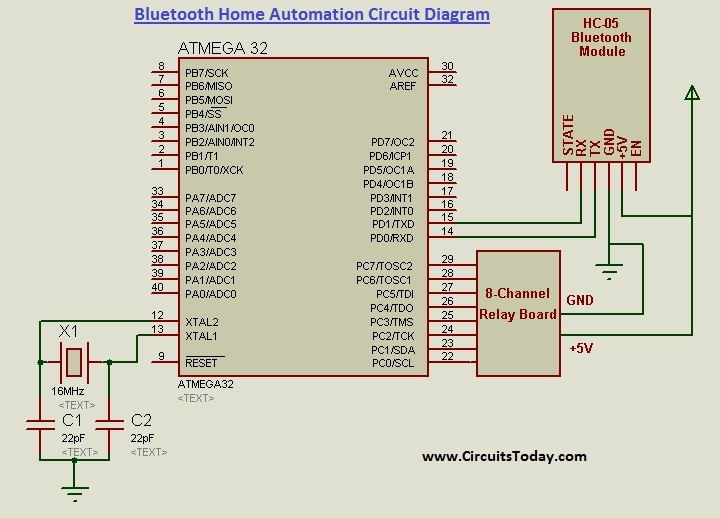
The output of the SMPS/AC-DC Adapter is 12V, 0-2 Amps. Either LM2576 or voltage regulator 7805 of 1A current rating can be used. This is not shown in the circuit diagram.
Component List
| S.No. | Component/Part | Specification/Value | Qty. |
|---|---|---|---|
| 1. | Microcontroller | ATMEGA 32 | 1 |
| 2. | IC Base | 40-Pin | 1 |
| 3. | Crystal Oscillator | 16 MHz | 1 |
| 4. | Capacitors-Ceramic | 22pF | 2 |
| 5. | Voltage Regulator | 7805/LM 2576 | 1 |
| 6. | Heat Sink | For voltage regulator | 1 |
| 7. | Berg Strips for inserting Bluetooth module | Female Type | 6 Pins |
| 8. | Wired connector | 10-Pin | 1 |
| 9. | Relay Board | 5V Coil;8-Channel | 1 |
| 10. | Bluetooth Module | HC-05 | 1 |
| 11. | AC/DC Adapter | 12V,0-2 Amps | 1 |
| 12. | General Purpose PCB | As required | |
| 13. | Enclosure | ABS / Electrical switch board | 1 |
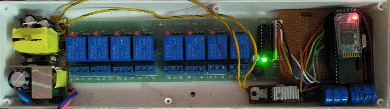
Hardware Kit – Photograph
Output Demo Video
So that’s it! We have finished our tutorial on building a home automation project kit using AVR and Bluetooth Module. Build yourself and see how it goes!
3 Comments
I used the code you attached..but.. Port c pins..3,4 and 7 are always high..and r not communicating with the Bluetooth module..can u suggest the solution..??
I am interested to read and understand your publications about the new ventures in the field of ELECTRONICS WORLD. I wish all the memembers in this TEAM.
With regards.
DAS