What is a Blue Pill board?
Unlike, the famous Arduino UNO board, the Blue Pill is a high-performance ARM Cortex-M3 32-bit microcontroller development board that works at a maximum operating frequency of 72MHz. As you already know that Arduino UNO board has some limitations when it comes to more complex projects because of its limited Input/Output pins, low-resolution ADC, slower PWM speed and fewer interrupt pins. These limitations can be overcome by using this Blue Pill board. It has more input/output pins, 12-bit ADCs, more external interrupt pins, higher PWM speed, and many more features. The Blue Pill board has more than one I2C, UART, and SPI port, which helps in communication with other devices way faster than that of the Arduino UNO board. It has lots of I/O pins which make it easier to connect more sensors, modules, and other electronic components to the board. In order to program this Blue Pill board, we will use the same Arduino IDE software and will use the same sets of instructions that we use for programming the Arduino UNO board.
Specifications of the Blue Pill Board
- Microcontroller Name: STM32F103C8T6
- Maximum Frequency: 72MHz
- Flash memory: 64 or 128 Kb
- SRAM: 20Kb
- Input voltage: 2-3.3V DC
- 16 channels ADC
- I/O Ports: 37
- Timers: 7
- Two I2C ports
- Three UART Ports
- TWO SPI ports
- CAN interface
Applications of the Blue Pill Board
- Multi-rotors
- Robotics and automation
- Sensor development
- Rapid prototyping
- Consumer products
Blue Pill Vs Arduino UNO
|
Specification |
Blue Pill |
Arduino UNO |
|
Processor |
STM32F103C8T6 |
Atmega328P |
|
Architecture |
ARM Cortex-M3 32-bit RISC |
AVR 8-bit RISC |
|
Operating Frequency |
72MHz |
16MHz |
|
Operating Voltage |
5V DC |
3.3V DC |
|
UART Port |
3 |
1 |
|
SPI Port |
2 |
1 |
|
I2C Port |
2 |
1 |
|
Digital I/O Pins |
37 |
14 |
|
Analog pins |
10 |
8 |
Blue Pill Board configuration
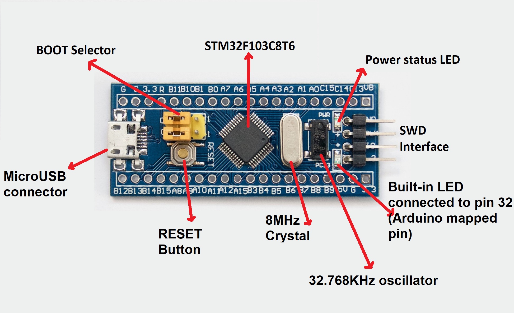
STM32F103C8T6: This is the main microcontroller IC used by the Blue Pill board.
MicroUSB connector: Used for connecting the board to the laptop.
Reset button: Used for resetting the board.
8MHz Crystal: This crystal is used by the main STM32 microcontroller.
32.768KHz Oscillator: This oscillator is for Real-time Clock(RTC).
Power Status LED: This LED is used for indicating power.
Built-in LED: This LED is connected to pin PC13(Arduino mapped pin 32).
BOOT selector: These pins are used for selecting between the BOOT1 and BOOT0. For BOOT0 connect the jumpers to top pins and for selecting BOOT1, connect the jumpers to the bottom pins. If BOOT0 is selected, when you reset the board or give power to the board the code will remain stored on the board. If BOOT1 is selected, when you reset the board or give power to the board the previous program stored on the board gets erased.
SWD Interface: Used for programming and debugging using ST-Link
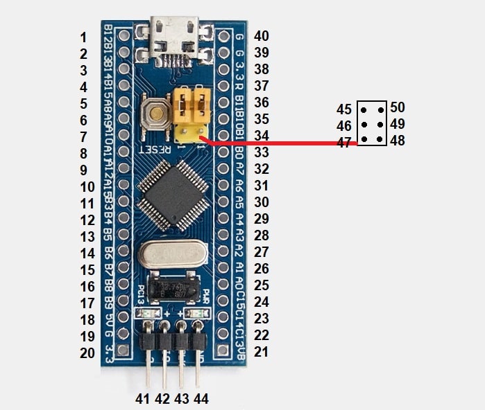
Pin configuration of the Blue Pill Board
|
PIN Number |
Board Pins |
Arduino Pins |
Other pin uses |
PWM Pins |
ADC Pins |
|
1 |
PB12 |
28 |
SS2 |
||
|
2 |
PB13 |
29 |
SCK2 |
||
|
3 |
PB14 |
30 |
MISO2 |
||
|
4 |
PB15 |
31 |
MOSI2 |
||
|
5 |
PA8 |
8 |
PWM |
||
|
6 |
PA9 |
9 |
TX1 |
PWM |
|
|
7 |
PA10 |
10 |
TX2 |
PWM |
|
|
8 |
PA11 |
11 |
USB- |
||
|
9 |
PA12 |
12 |
USB+ |
||
|
10 |
PA15 |
15 |
|||
|
11 |
PB3 |
19 |
|||
|
12 |
PB4 |
20 |
|||
|
13 |
PB5 |
21 |
|||
|
14 |
PB6 |
22 |
SCL1 |
PWM |
|
|
15 |
PB7 |
23 |
SDA2 |
PWM |
|
|
16 |
PB8 |
24 |
PWM |
||
|
17 |
PB9 |
25 |
PWM |
||
|
18 |
5V |
||||
|
19 |
GND |
||||
|
20 |
3.3V |
||||
|
21 |
VBAT |
||||
|
22 |
PC13 |
32 |
LED |
||
|
23 |
PC14 |
33 |
|||
|
24 |
PC15 |
34 |
|||
|
25 |
PA0 |
0 |
PWM |
ADC0 |
|
|
26 |
PA1 |
1 |
PWM |
ADC1 |
|
|
27 |
PA2 |
2 |
TX2 |
PWM |
ADC2 |
|
28 |
PA3 |
3 |
RX2 |
PWM |
ADC3 |
|
29 |
PA4 |
4 |
SS1 |
ADC4 |
|
|
30 |
PA5 |
5 |
SCK1 |
ADC5 |
|
|
31 |
PA6 |
6 |
MISO1 |
PWM |
ADC6 |
|
32 |
PA7 |
7 |
MOSI1 |
PWM |
ADC7 |
|
33 |
PB0 |
16 |
PWM |
ADC8 |
|
|
34 |
PB1 |
17 |
PWM |
ADC9 |
|
|
35 |
PB10 |
26 |
TX3/ SDA2 |
||
|
36 |
PB11 |
27 |
RX3/ SCL2 |
||
|
37 |
RESET |
||||
|
38 |
3.3V |
||||
|
39 |
GND |
||||
|
40 |
GND |
||||
|
41 |
3.3V |
||||
|
42 |
PA13 |
34 |
JTMS/ SWDIO |
||
|
43 |
PA14 |
37 |
JTCK/ SWCLK |
||
|
44 |
GND |
||||
|
45 |
GND |
||||
|
46 |
PB2 |
18 |
BOOT1 |
||
|
47 |
3.3V |
||||
|
48 |
3.3v |
||||
|
49 |
BOOT0 |
||||
|
50 |
GND |
||||
Important note: While writing the Arduino code, we will be using the pin number as mentioned in the Arduino pins column that is highlighted with blue color.
Programming the Blue Pill board with Arduino IDE
Step1: Get ready with your Blue Pill Board.
Step2: Power the Blue Pill board with a USB power supply of 5 volts.
Step3: Connect the USB to UART converter as shown in the diagram.
Step4: Select 3.3v mode in USB to the serial converter by connecting the jumpers as shown in the diagram.
Step5: Connect the USB to UART converter to the laptop.

Step6: Open the Arduino IDE
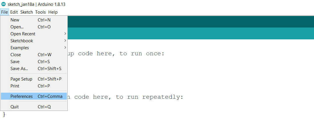
Step7: Click on the file option

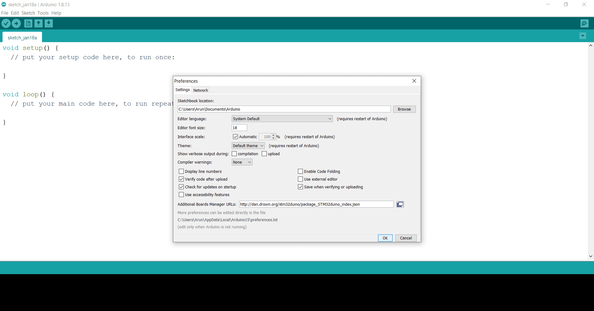
Step8: Click on the Preferences
Step9: Paste this link in the additional board manager URLs : http://dan.drown.org/stm32duino/package_STM32duino_index.json

Step10: Click on the OK
Step11: Click on the tools
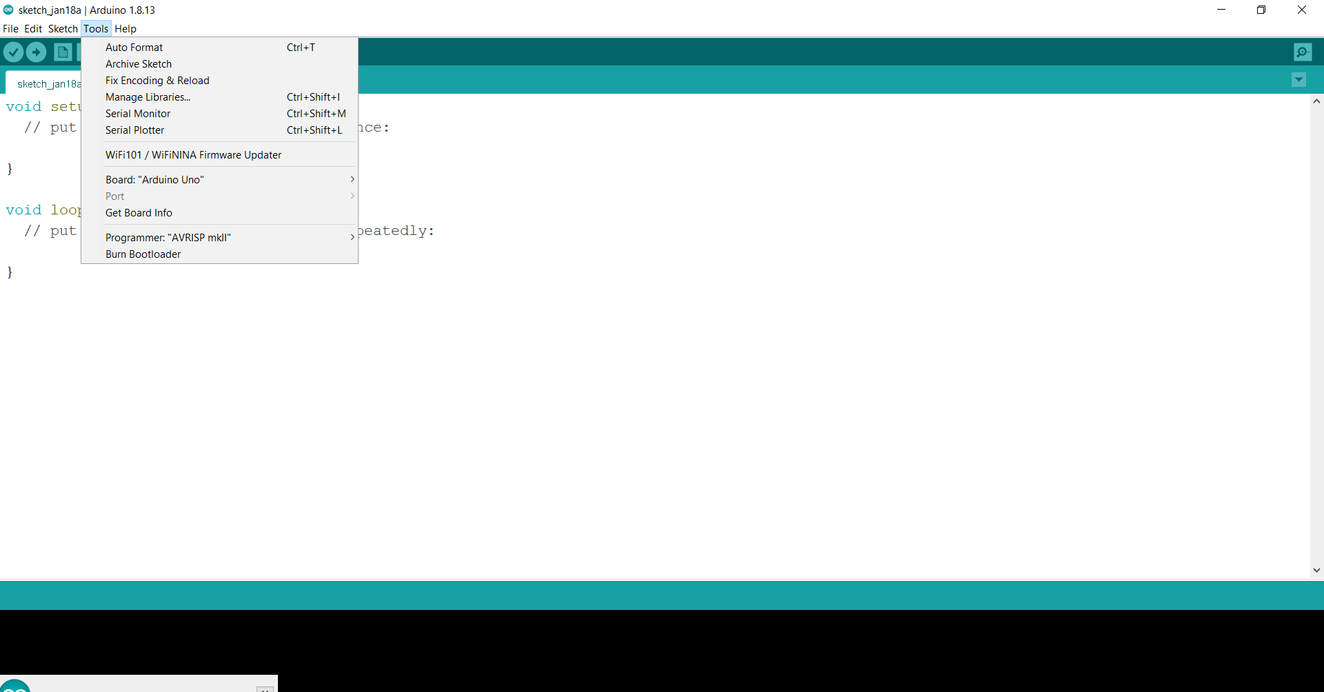
Step12: Click on the Board
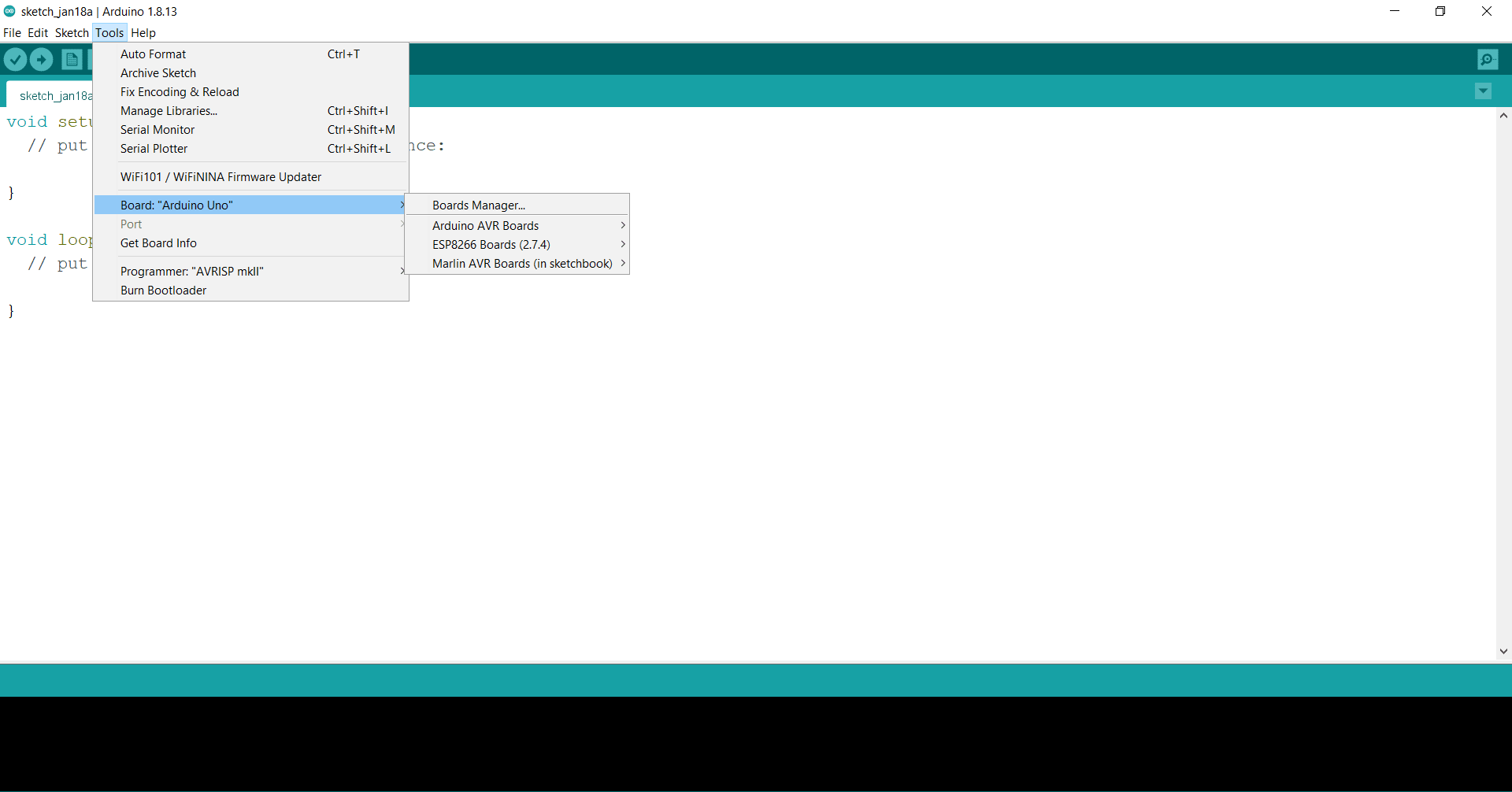
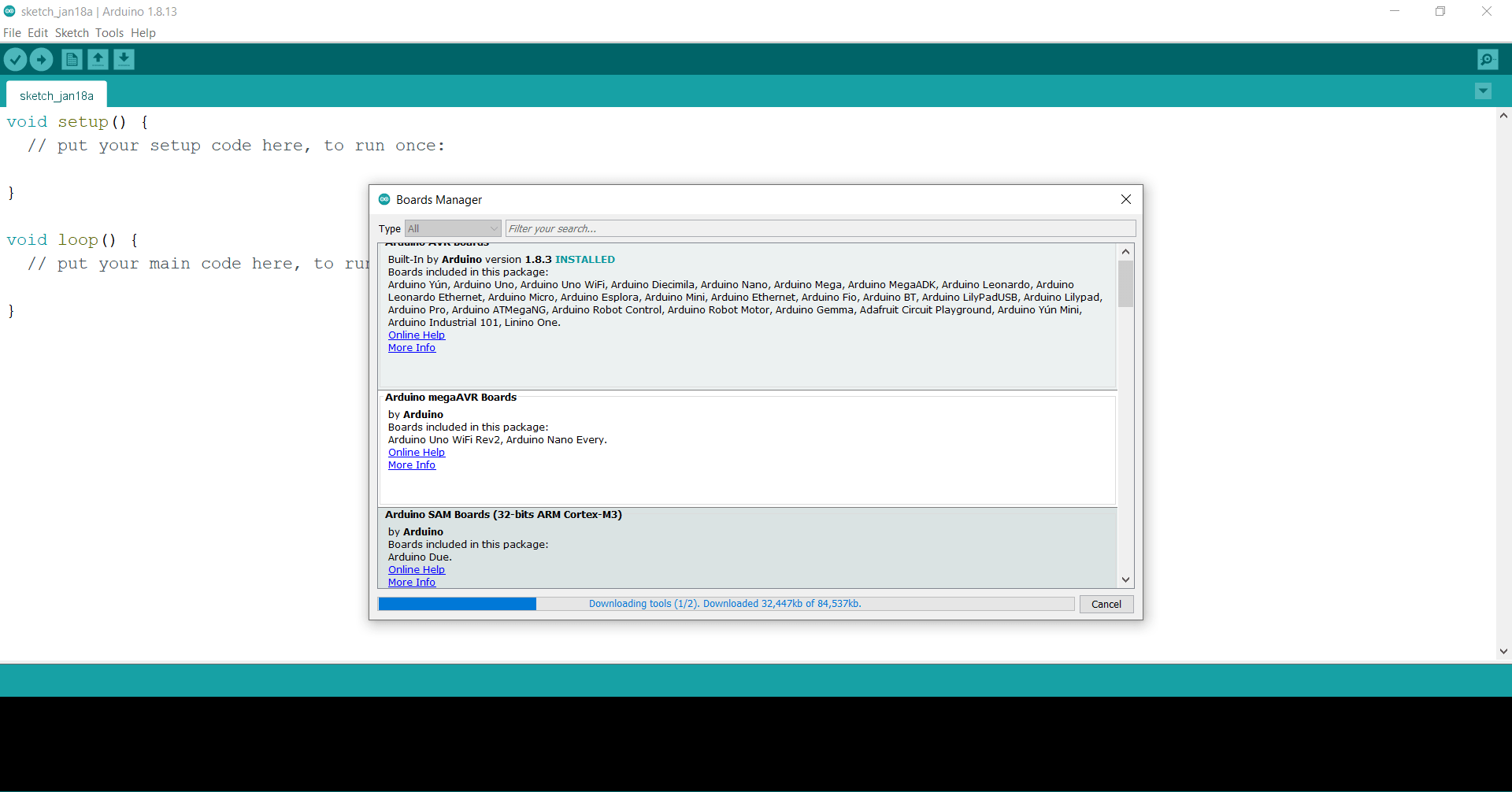
Step13: Click on the Board manager and wait for some time
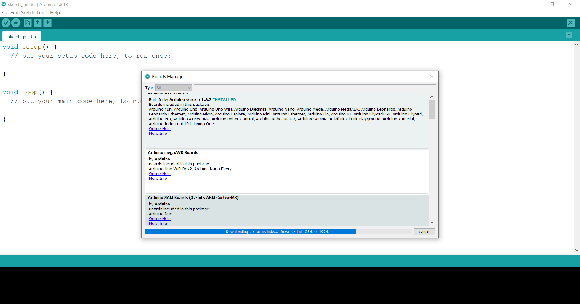
Step14: Scroll down and find the STM32F1xx/GD32F1xx Board and then click on install. Wait for some time till the board is downloaded.

Step15: Close the board manager if you got this message

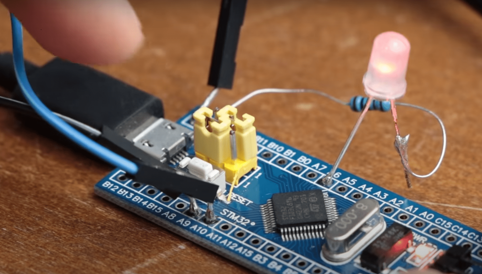
Make sure your Blue Pill board is connected to the laptop with the help of a USB to UART converter. Now, we will upload our first LED blinking code to the board. Paste this code in Arduino IDE. Connect an LED to the A6 pin of the board as shown in the diagram. In terms of Arduino mapped pins, A6 pin of the Blue Pill board is a D6 pin in Arduino, you can refer to the pin configuration table for this. While writing your code for the Blue pill board, you just have to use the pin number as per the Arduino mapped pins. Rest all the commands are the same.
void setup()
{
pinMode(6,OUTPUT);
}
void loop()
{
digitalWrite(6,HIGH);
delay(1000);
digitalWrite(6,LOW);
delay(1000);
}
Circuit diagram for connecting an LED to the Blue Pill board

In order to upload the code to the Blue Pill board follow the following steps.
Step1: Click on the tools and then click on board
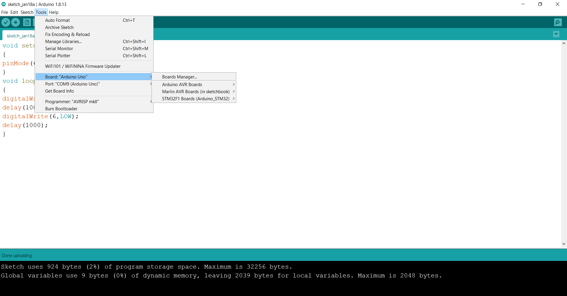
Step2: Click on the STM32F1 boards
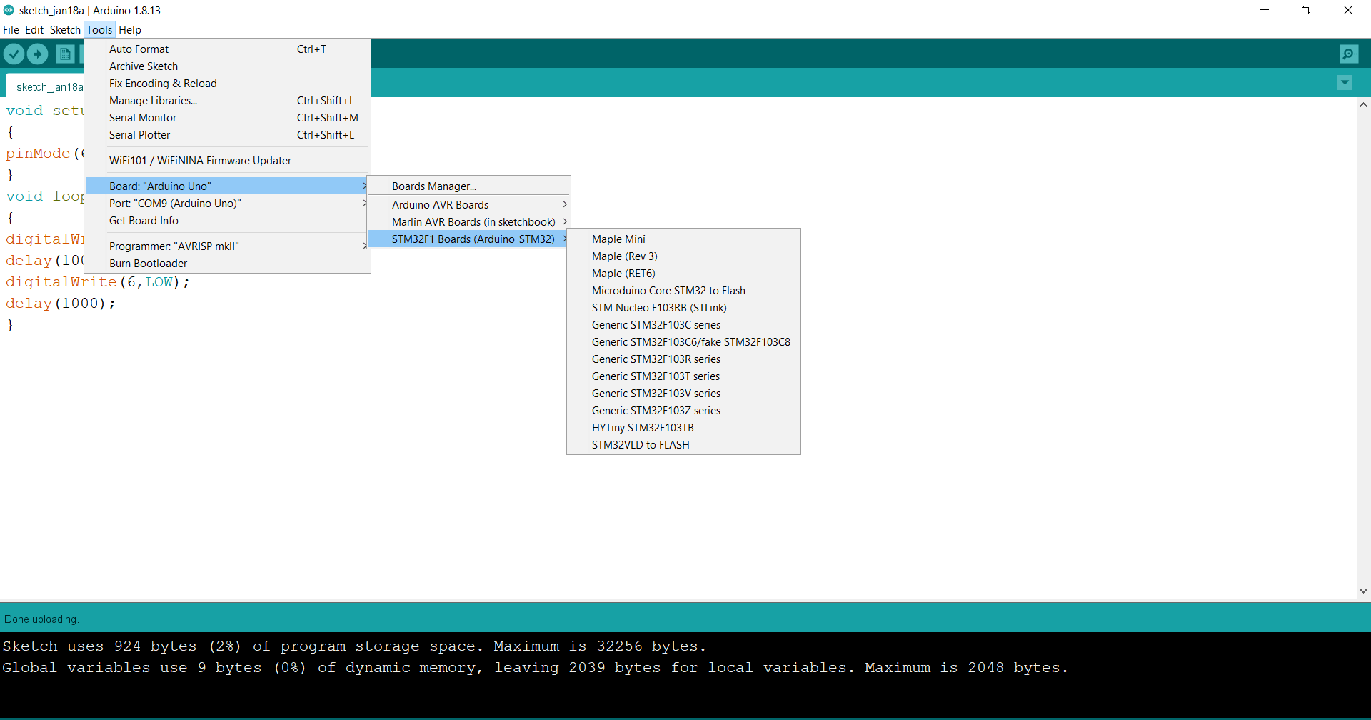
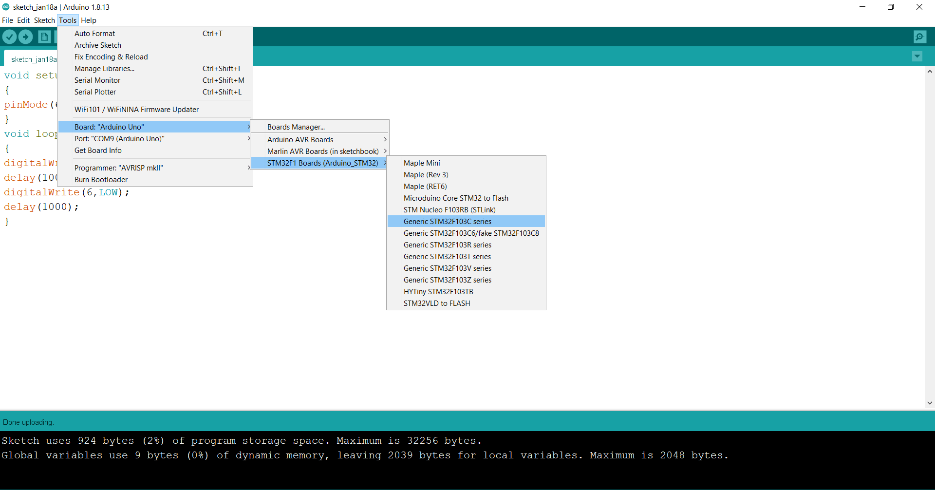
Step3: Click on the Generic STM32F103C series
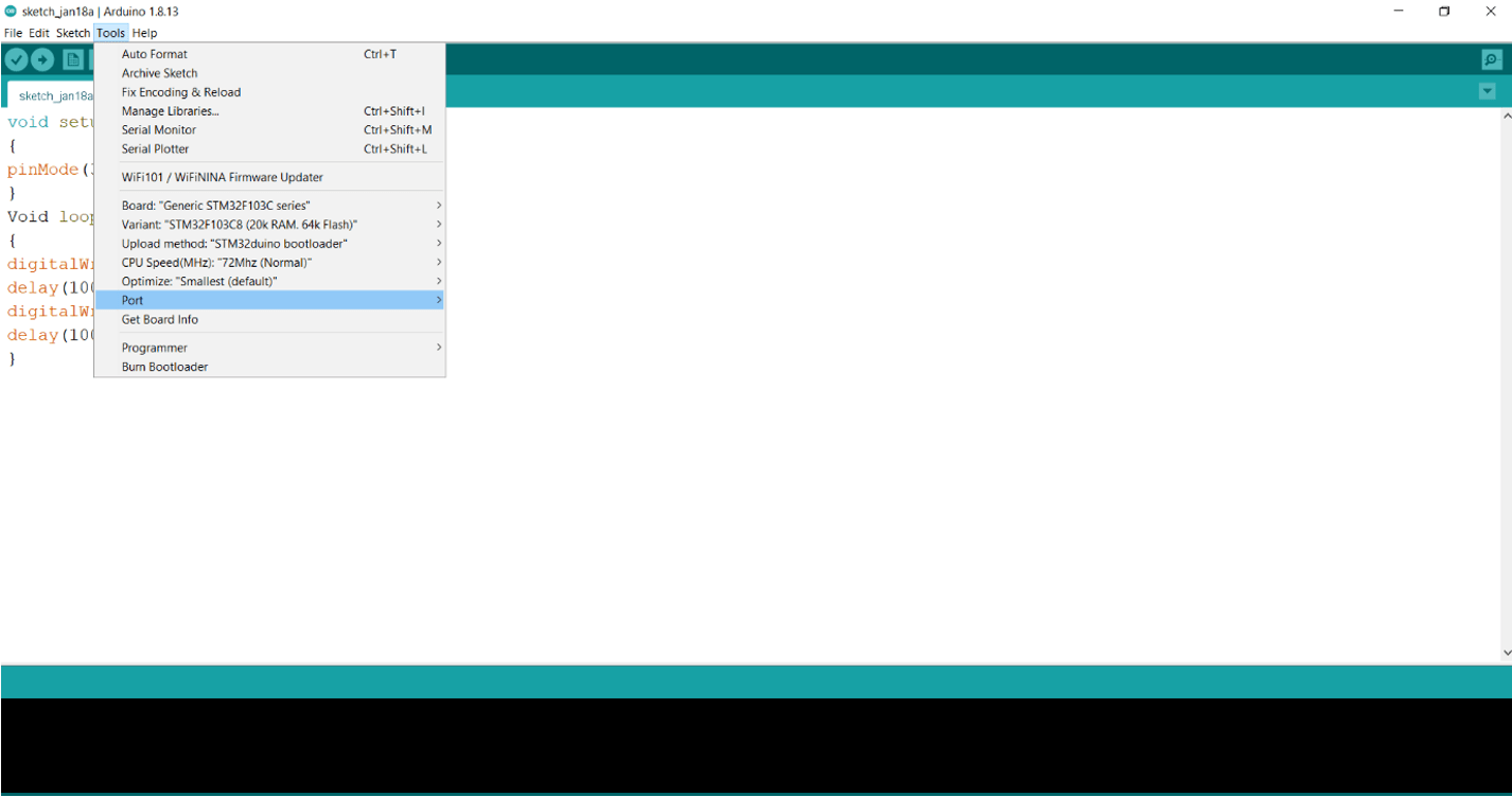
Step4: Select the port
Step5: Click on the upload button and after uploading the LED will start blinking.
I hope, you have successfully integrated your Blue Pill board with Arduino IDE. If you have any doubt, you can comment below or you can email us.
Comments are closed.