A digital oscilloscope finds its vast use among engineering students and circuit enthusiasts. It is known to be one of the best and most able device to capture, analyze and study the salient features of electrical signals. Digital oscilloscopes also finds its use in motor vehicle testing, telecom engineering, vehicle ignition systems, and also medical instruments like ECG’s.
A digital oscilloscope is basically an analog oscilloscope that uses an analog to digital converter (ADC) to transform the measured voltage into digital data. The device uses a sampling system to acquire the incoming waveform, and stores them until sufficient samples are achieved to represent a waveform. These signals are then rearranged to show them diagrammatically on a screen. These signals can be viewed through their different parameters like voltage, current or even magnetic strength. Digital oscilloscopes will remain an integral part of research and academia for some time to come, as signals are to be studied for almost all devices.
We have already discussed about the basic oscilloscope guide, where all the parameters of an oscilloscope (analog and digital) are explained in detail. You can know more about the best analog oscilloscopes (CRO) to get more knowledge.
Digital oscilloscopes are mainly divided into four types, depending on the architecture. A detailed review of some of the best digital oscilloscopes depending on their architecture will be given below. We have provided sources to buy some of the best digital osilloscopes online as well.
- Digital Storage Oscilloscope (DSO)
- Digital Phosphor Oscilloscope (DPO)
- Digital Mixed Signal Oscilloscope (MSO)
- Digital Mixed Domain Oscilloscope (MDO)
Digital Storage Oscilloscope (DSO)
The DSO is one of the most basic and conventional type, and also one of the most preferred type of digital oscilloscopes. Although a Digital Oscilloscope and a Digital Storage Oscilloscope are somewhat different in their functions, these two names are often used interchangeably. When comparing to an analog oscilloscope, a DSO uses a digital memory to store the data. Unlike an analog oscilloscope, the DSO converts the analog data into a digital waveform with the help of an analog-to-digital converter (ADC).
The DSO can be used to measure the maximum frequency, but will depend on two criterion’s:
The sampling rate provided by the scope and the nature of the converter. The converter could be analog or digital and strictly depends on the manufacturer’s preference. The traces in DSO can be displayed almost instantaneously as they are non-stored traces. These traces will be bright and well defined so that the user can get an exact idea of the output waveform. These traces provide their feedback in terms of waveforms as well as numerical values. This is done by the accurate analyzation of the stored traces. The trace can be shown on the front screen so that the user can visualize the waveform. To know more about it, the user has options to magnify the waveform , increase/decrease the brightness of the traces, and many more options are provided to acquire the data.
The digital screen consists of the parameters time period and input voltage in the X and Y axis. There are controls to provide 3-D styles and can display many waveforms to compare. Nowadays, DSO’s have internal memories that can store traces to refer later. Some best selling DSO’ are listed below.
Rigol DS1054Z, 50 Mhz Digital Storage Oscilloscope
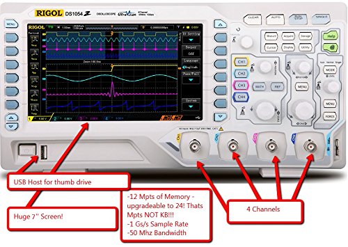
One of the main features of the Rigol DS1054Z DSO is the UltraVision Technology. This innovation provides a memory depth of 12 Mpts and can be upgraded to 24 Mpts . This product also provides quick focus controls to help you analyze in detail a certain recorded waveform.
The device is also known for its clear visibility. With the help of a 7 inch display and a resolution of 800×480 pixels, you can view all the channel waveforms in one screen with ease. This helps in better comparison of the signals.
For the given price the DS1054Z model has an ultra-fast sampling rate which helps you to capture upto 30.000 waveforms per second in a single screen. This feature when added with its good memory depth and 1 GS/s sampling rate is sure to help you in most industrial and circuit applications.
The internal design and architecture has made this RIGOL DSO highly efficient and fast in solving complex signal calculations. This is the best digital oscilloscope for all electronics hobbyists, testing industries and students. More features are given below.
Features/Specifications
| Model | Rigol DS1054Z |
|---|---|
| Bandwidth | 50 MegaHertz |
| Channels | 4 |
| Real time Sampling Rate | 1 GSa/s |
| Equivalent Sampling Rate | 25 GSa/s |
| Memory Depth | 12 Mpts |
| I/O Sample Rate | 200 MSa/s |
| Rise Time | Less than 3.5 nanoseconds |
| Input Impedance | 1 MegaOhm / 13 PicoFarads |
| Timebase Range | 5 nanoseconds/div to 50 seconds/div |
| Vertical Sensitivity | 1 millivolts to 10 volts/div |
| Vertical Resolution | 8 Bits |
| Trigger Source | CH1, CH2, EXT, Ext/5, AC Line |
| Trigger Types | Edge, Pulse, Video, Slope, Alternative |
| Mathematical Operations | Add, SUB, MUL, DIC, FFT |
| Digital Filters | HIGH, LOW, Band Pass, Band Stop |
| Maximum Input Voltage | CAT I 300 Vrms, CAT II 100 Vrms, transient overvoltage 1000 Vpk With RP2200 10:1 probe: CAT II 300 Vrms |
| Interface | LAN / Ethernet, LXI, USB Host, USB |
| Display | 7 inches, color TFT (800x480), LCD |
| Power | (100-240) Volts AC, (45-440) Hertz, 50 Va Max. |
| Dimensions | 313.1 mm width × 160.8 mm height ×122.4 depth mm |
Siglent SDS1052DL, 50 MHz Digital Storage Oscilloscope with Frequency Counter
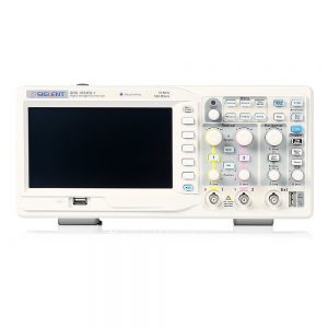
When comparing the features and price of this DSO, it is relatively inexpensive and is filled with features which attracts all circuit enthusiasts and technicians who prefer a 50 MHz DSO scope. Due to its light weight (5.5 lbs) and small dimensions (323mm width × 157mm height × depth 135mm), the SDS1052DL model is known for its portability and use in different fields. The easy navigation controls and quick analytic architecture will make your work more efficient and fast. It’s different triggering options, complex mathematical processing and digital filtering options will surely help you manage all the areas of signal processing. The device is also designed for self calibration and also allows waveform printing. It includes 20 automatic measurement configurations as well. More parameters and their values along with other features are provided below.
Features/Specifications
| Model | Siglent SDS1052DL |
|---|---|
| Bandwidth | 50 MegaHertz |
| Channels | 2 |
| Real time Sampling Rate | 500 MSa/s |
| Equivalent Sampling Rate | 50 GSa/s |
| Memory Depth | 32K |
| Rise Time | Less than 7 nanoseconds |
| Input Impedance | 1 MegaOhm / 17 PicoFarads |
| Timebase Range | 10 nanoseconds/div to 50 seconds/div |
| Vertical Sensitivity | 2 millivolts to 10 volts/div |
| Vertical Resolution | 8 Bit |
| Trigger Source | CH1, CH2, EXT, Ext/5, AC Line |
| Trigger Types | Edge, Pulse, Video, Slope, Alternative |
| Mathematical Operations | Add, SUB, MUL, DIC, FFT |
| Digital Filters | HIGH, LOW, Band Pass, Band Stop |
| Maximum Input Voltage | ±400V (DC+AC Pk-Pk), CAT I, CAT II |
| Internal Storage | 2 groups of reference waveform, 20 groups of setting, 10 groups of waveform |
| External Storage | Bitmap, CSV, Waveform, Setting save |
| Language | English, French, German, Russian, Chinese, Arabic, French, Japanese, Korean, Italian, Portuguese |
| Interface | USB Host and Device / RS-232, Pass/Fail out |
| Display | 7 inches, color TFT (480x234), LCD |
| Power | (100-240) Volts AC, (45-440) Hertz, 50 Va Max. |
Siglent SDS1102CML, 100 MHz Digital Storage Oscilloscope
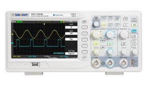
The Siglent SDS1102CML model has 2 channels with a bandwidth of 100 MegaHertz. It has a single real-time sampling rate of up to 1 GSa/s and a memory depth of 2 Mpts. The device comes along with a probe (1:1, 10:1), a power cord, an USB cable, an Easy Scope CD, and a user manual. An LCD screen is used to display the waveforms. The screen is 7” in diameter and has a full-color option, which helps in picking out the required waveform.
In order to filter out the noise from the output data, filters like the HIGH pass, LOW pass, BAND pass and STOP filters are provided in the CML range. Edge trigger, Pulse Trigger, Video, Slope and Alternative trigger are also provided.
USB connectivity is provided along with RS-232 ports so that the user can extract data whenever needed. A software is also included for the user to analyze the data in detail.
Features/Specifications
| Model | Siglent SDS1102CML |
|---|---|
| Bandwidth | 100 MegaHertz |
| Channels | 2 |
| Real time Sampling Rate | 1 GSa/s |
| Equivalent Sampling Rate | 50 GSa/s |
| Memory Depth | 2 Mpts |
| Rise Time | Less than 3.5 nanoseconds |
| Input Impedance | 1 MegaOhm / 17 PicoFarads |
| Timebase Range | 2.5 nanoseconds/div to 50 seconds/div |
| Vertical Sensitivity | 2 millivolts to 10 volts/div |
| Vertical Resolution | 8 Bit |
| Trigger Source | CH1, CH2, EXT, Ext/5, AC Line |
| Trigger Types | Edge, Pulse, Video, Slope, Alternative |
| Mathematical Operations | Add, SUB, MUL, DIC, FFT |
| Digital Filters | HIGH, LOW, Band Pass, Band Stop |
| Maximum Input Voltage | ±400V (DC+AC Pk-Pk), CAT I, CAT II |
| Internal Storage | 2 groups of reference waveform, 20 groups of setting, 10 groups of waveform |
| External Storage | Bitmap, CSV, Waveform, Setting save |
| Language | English, French, German, Russian, Chinese, Arabic, French, Japanese, Korean, Italian, Portuguese |
| Interface | USB Host and Device / RS-232, Pass/Fail out |
| Display | 7 inches, color TFT (480x234), LCD |
| Power | (100-240) Volts AC, (45-440) Hertz, 50 Va Max. |
| NIST | Traceable Calibration Certificate Available |
Owon SDS7102, 2-Channel, Deep Memory Digital Storage Oscilloscope with LAN Interface
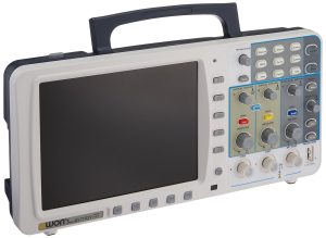
The Owon SDS7102 model digital storage oscilloscope is compact enough (155 height x 340 width x 70 depth in mm) to carry around, but weighs about 2 kgs. The controls of the DSO helps in obtaining advanced triggering, three math functions with FFT. There are 20 default automatic measurements along with auto-scale function and pass/fail testing. One side of the DSO is allotted for VGA portability and USB connectivity. Details about USB connectivity is not provided in the manual though. A Windows Microsoft compatible software is used to transmit and receive data.
An additional feature is that the device can be made to operate on battery mode. An additional power button is provided to charge the battery while keeping the rest of the device turned OFF. This device is apt for on-site and portable applications. When batteries are installed the weight of the device further increases.
Though the DSO looks really compact, it does have a small fan installed inside to drive away the heat. The 8-inch display is given an anti-glare coating that it can viewed clearly in open areas. A sampling depth of 10M is enough to capture a lot of data at a time for receiving waveforms. An external channel is provided so that a third source can be triggered while data acquisition is enabled from channels 1 and 2.
Am auto-scale function is provided to select the correct settings for displaying a waveform. The deep memory enables to store up to 15 waveforms for later use. The cursor measurement includes voltage difference and time difference between cursors.
Features/Specifications
| Model | Owon SDS7102 |
|---|---|
| Bandwidth | 100 MegaHertz |
| Channels | 2 |
| Real time Sampling Rate | 500 MSa/s (1 GS/s interleaved) |
| Equivalent Sampling Rate | 50 GSa/s |
| Memory Depth | 10 Mpts |
| Rise Time | Less than 3.5 nanoseconds |
| Timebase Range | 2 nanoseconds/div to 5 seconds/div |
| Vertical Sensitivity | 2 millivolts to 10 volts/div |
| Vertical Resolution | 8 Bit |
| Trigger Source | CH1, CH2, EXT |
| Trigger Types | Edge, Pulse, Video, Slope, Alternative |
| Mathematical Operations | Add, SUB, MUL, DIV, FFT |
| Language | English, French, German, Russian, Chinese, Arabic, French, Japanese, Korean, Italian, Portuguese |
| Interface | USB Host and Device / RS-232, LAN, Pass/Fail out |
| Display | 8 inches SVGA, color TFT (800x600), LCD |
| Power | (100-240) Volts AC, (50-60) Hertz, 50 Va Max |
Digital Phosphor Oscilloscope (DPO)
When comparing a DSO to a DPO, a DSO is a real-time sampling oscilloscope, while a DPO is has an additional ‘frequency-of-occurrence’ element which helps the signal to show a real third dimension. In DSO a high sampling rate ADC is used to seize the signals in a single acquisition. The DSO does not use repeating acquisitions to build up sufficient samples to represent the working signal. Thus, a DSO is a DPO if it adds the third frequency of occurrence axis in addition to the time period and voltage axis. This additional axis constitutes the trace intensity on a scope display. But, a DPO is definitely a DPO.
A DPO has a better signal processing capability due to its variance in architecture than other conventional storage types. This unique architecture consists of a parallel processing method rather than the common serial processing technique used in DSO’s. A dedicated processor is also provided to effortlessly copy the transient events that occur in digital systems.These events include false pulses, glitches and transition errors. It also mirrors the display characteristics of an analog oscilloscope, and depicts the signal in 3D, in real time.
In a Digital Phosphor Oscilloscope, the signal passes through a vertical amplifier, and then fed to an ADC. From here, unlike a DSO, a DPO uses a parallel processor, which captures and stores the waveforms. In the serial processing technique of a DSO, this process could take more time. But in a DPO, the signals are not limited and can be captured individually with the activity of the display. Thus, a much more intense image is displayed on the screen with better clarity. This is one reason that many believe that the display is of phosphor material. But it is not so.
Every time a waveform passes through the processor, it’s image is created in the DPO memory. Each cell depicts a screen location. When the data passes through many tme the intensity of the waveform in the display increases. Thus, the display shows an intense waveform in the areas, in proportion to the occurrence of signal at each point. The parallel processor operation is used for other factors like measurement control, device control, display measurement and so on. This increases the operation speed of the scope and thus
The more times data is stored into a location, the greater the intensity attached to it. In this way intensity information builds up in cells where the waveform passes most often. The overall result is that the display reveals intensified waveform areas, in proportion to the frequency of occurrence of the signal at each point. This has the same appearance as those displayed on an analogue phosphor oscilloscope, and this gives rise to the name.
Effectively the processor within the DPO operates in parallel with the acquisition system for display management, measurement control, and overall instrument control. In this way its operation does not affect the acquisition speed of the overall scope. Thus a real time display is achieved to capture transient and repetitive waveforms.
One of the best selling digital phosphor oscilloscope (DPO) is reviewed below. Take a look.
Tektronix DPO2014B, 100 MHz 4 channel Digital Phosphor Oscilloscope
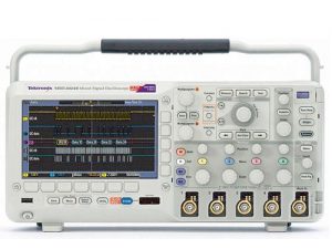
The DPO2014B model by Tektronix is known to be integrated with some feature rich tools for debugging mixed signal designs: and that too at an affordable cost. You can find and solve waveform complications easily with the help of the 4 analog channels available. A record length of 1 Megapoints is provided for all the channels, so that you can capture long windows of signal activity with ease. Another unique feature provided by this model includes the Wave inspector controls for use in rapid waveform generation, and automated serial and parallel bus analysis. The filter Vu Variable LPF allows for removal and unwanted signal noise while simultaneously capturing HF events.
The whole device is compact (height 180 x width 77 x depth 134) and weighs just 7.9 pounds. The device comes with a five year warranty. One of the biggest advantage of this device is the speed that every one of their features provides: in either debugging your circuit design – from quick analysis of a waveform variation, to searching uyour waveform and characterizing your waveform behaviour.
The 2014B model offers a far insight in discussing the problems and thus giving you a clear idea of the circuit design. You get to know the true nature of the waveforms and the abnormalities present, all through the capture rate of 5000 waveforms.
Analyzing the rise time, pulse width, noise sources and other parameters is made simple using the different tools provided for automated measurements (24 types), and waveform and screen based cursor applications.
The front panel has a USB 2.0 Host Port in order to provide quick and easy data storage. The rear panel has a USB 2.0 Device Port to directly connect to a personal computer or to connect to a printer. You can connect to other networks using the 10/100 Ethernet port. You can view the waveform and other displays on a projector or a big screen using a Video Outport.
A Play/Pause button is provided in the front end panel so that you can move the pass through the waveform to check for problems. There are settings to control the speed and direction of the waveform. Easy access buttons are provided for this purpose.
You can place multiple marks on the displayed waveform using the Set Mark button on the front panel. Channeling between the marks can be carried easily by pressing the left and right keys.
Features/Specifications
| Model | Tektronix DPO2014B |
|---|---|
| Bandwidth | 100 MegaHertz |
| Channels | 4 Analog and 16 Digital channels |
| Real time Sampling Rate | 1 GS/s on all channels |
| Rise Time | Less than 3.5 nanoseconds |
| Main Trigger Modes | Auto, Normal, Single |
| Trigger Holdoff Range | 20 nanoseconds to 8 seconds |
| Display Graticules | Full, Grid, Cross Hair, Frame |
| Maximum Record Length | 1 MegaPoints |
| Minimum Detachable Pulse Width | 5 nanoseconds |
| Timebase Range | 4 nanoseconds/div to 100 seconds/div |
| Vertical Sensitivity | 2 millivolts to 5 volts/div |
| Vertical Resolution | 8 Bits |
| Trigger Types | Edge, Pulse, Video, Runt, Logic, Slope, Setup and Hold |
| Mathematical Operations | Add, SUB, MUL, DIV, FFT |
| Language | English, French, German, Russian, Chinese, Arabic, French, Japanese, Korean, Italian, Portuguese |
| Interface | USB Host and Device / RS-232, LAN, Auxiliary, Kensington Style Lock, Probe Compensator Output, Video Out Port |
| Display | 7 inches 180 mm, widescreen TFT- LCD color display (480x234 MQVGA) |
| Power | (100-240) Volts AC, (45-65) Hertz |
Digital Mixed Signal Oscilloscope (MSO)
A digital mixed signal oscilloscope (MSO) has a combination of two to four analog channels and more than ten digital channels. The MSO provides better precision in timing correlated analog and digital channels, thus combining the use of an oscilloscope and a logic analyzer. The desired digital channels can be grouped and provided in the output as a bus with each bus value provided in the display bottom in terms of hex, ASCII or level for digital to analog testing. Another advantage is the use of advanced triggering for both analog and digital channels. Using MSO faults in data transmission signals can be sorted through analytic methods and serial bus decoding.
The MSO needs to provide the functions of a digital oscilloscope as well as a logic analyzer. A logic analyzer usually has 32 channels with use in serial and parallel bus protocols triggering and decoding. The function of mixed signal oscilloscope as a digital oscilloscope and a logic analyzer is different. When used as a signal oscilloscope all the analog channels use an ADC to convert the analog signals to digital signals. Further processing is done to display the analog version of the signals.
The function of the MSO as a logic analyzer has the channels to convert the signals into digital format. These signals are then displayed on the screen as high or low level, and no analog information is provided. The main use of the logic analyzer is to provide full visibility of the logic on a circuit. And this can be easily achieved as they do not need an ADC. If the analog version of the digital signal is needed by the user, it can be done by connecting to one of the analog channels.
Owon MSO7102TD, 100MHz Mixed Signal Oscilloscope with 16-Channel Logic Analyzer
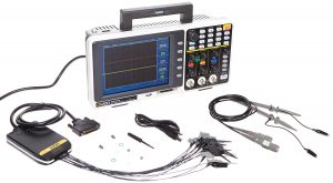
The OWON MSO7102TD model MSO is best known for it’s cross triggering applications with it’s 16-channel logic analyzer with a combination of 2 analog channels. This model provides a bandwidth of 100 MegaHertz for a real time sample rate of 500 MS/s and a record length of 2Mpts per channel. The model has a 100 MHz variant called the MSO8102ST with a sampling rate of 20 S/s to 1 GS/s per channel and a record length of 4 Mpts per channel.
This model has an overall height, width and length distribution of 180x120x370mm and weighs 4.8 pounds. The whole product includes probes, power cord, USB cable, CD-Rom, logic analyzer module, probe adjust, reference manual, battery (optional), and a bag (optional).
The trigger position can be done in pre, mid, and re-trigger settings. There are 10 storage settings and includes a data search feature. The logic analyzer has a sample rate of 20 S/s – 400 MS/s and a bandwidth of 66 MegaHertz. The threshold voltage has four settings at +/- 10 Volts. With a total of 16 channels, the record length is 4M/channel. 16K is provided when the sample rate is 400 MS/s. The input impedance is 1 MegaOhm.
The automatic measurements includes 20 types like Vpp, Vavg, RMS, Frequency, Period, Vmax, Vmin, Vtop, Vbase, Vwidth, Overshoot, Pre-shoot, Rise Time, Fall Time, +Width, -Width, +Duty, -Duty, Delay A to B (Up), Delay Ato B (Down).
Features/Specifications
| Model | Owon MSO7102TD |
|---|---|
| Bandwidth | 100 MegaHertz |
| Channels | 2 Analog and 1 External channel |
| Real time Sampling Rate | 500 MS/s (1 GS/s for single channel) |
| Rise Time | Less than 3.5 nanoseconds |
| Main Trigger Modes | Edge, Bus, Pattern, Sequential Queue, Data Width |
| Trigger Types | Edge, Video, Alternate |
| Probe Attenuation Factor | 1X, 10X, 100X, 1000X |
| Interpolation | (Sinx)/x |
| DC Gain Accuracy | +/- 3% |
| Cursor Measurement | Voltage and time difference between cursors |
| Maximum Record Length | 6K on each channel |
| Timebase Range | 2 nanoseconds/div to 100 seconds/div |
| Vertical Sensitivity | 2 millivolts to 10 volts/div |
| Vertical Resolution | 8 Bits (2 channels simultaneously) |
| Mathematical Operations | Add, SUB, MUL, DIV, FFT |
| Waveform Storage | 4 Waveforms |
| Interface | USB |
| Display | 8 inches, TFT- LCD color display (640x480) |
| Power | (100-240) Volts AC, 50 Hertz. CATII |
| Fuse | 1A, T Grade, 250 Volts |
Hantek MSO5202D, 200MHz Mixed Signal Oscilloscope with 16 Channel Logic Analyzer
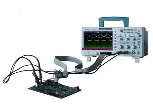
The Hantek MSO5202D model MSO with logic analyzer is known for its exquisite design with features that are way too many for the given price. The whole device weighs 4.5 Pounds and with all the components included weighs 7 Pounds. This lightweight device is very thin built as well, and can be easily carried to work. The display is large and crystal clear and is like watching a realistic waveform display. The device is compatible with operating systems like WIndows 2000, NT, 7, XP & Vista.
The device is equipped with some powerful trigger functions and more than 20 kinds of automatic measurement functions including Frequency, Period, Mean, Pk-Pk, Cycli RMS, Minimum, Maximum, Rise time, Fall Time, +Pulse Width, -Pulse Width, Delay 1-2 Rise, Delay 1-2 Fall, +Duty, -Duty, Vbase, Vtop, Vmid, Vamp, Overshoot, Preshoot, Period Mean, Period RMS, FOVShoot, RPREShoot, BWIDTH、FRF, FFR, LRR, LRF, LFR, LFF.
The logic analyzer has 16 sampled channels that are divided into two groups. The maximum input impedance is 200K (C=10p) and the input voltage range +/- 60 Volts. The logic threshold range comes between +/- 8 Volts and the maximum sample rate is 500 MegaHertz. The analyzer module is compatible to CCL, CMOS, and ECL logics. Measurement is done for period and frequency and has a sample depth of 512K.
Features/Specifications
| Model | Hantek MSO5202D |
|---|---|
| Vertical System Bandwidth Limit | 20 MegaHertz |
| Channels | 2 Analog and 1 External channel |
| Record Length | 1M |
| Input Impedance | 1 MegaOhm |
| Real time Sampling Rate | 500 MS/s (1 GS/s for single channel) |
| Equivalent Sample | 25 GSa/s |
| Rise Time at BNC | 1.8 nanoseconds |
| Trigger Modes | Auto, Normal, Single |
| Trigger Types | Edge, Video, Pulse, Slope, OverTime, Alternate |
| Trigger Source | CH1, CH2, EXT, EXT/5, AC Line |
| Probe Attenuation Factor | 1X, 10X, 100X, 1000X |
| Interpolation | (Sinx)/x |
| DC Gain Accuracy | (+/-) 3% for Normal/Average Acquisition Mode (5V/div - 10mV/div) |
| DC Gain Accuracy | (+/-) 4% for Normal/Average Acquisition Mode (5V/div - 2mV/div) |
| Timebase Range | 4 nanoseconds/div to 40 seconds/div |
| Timebase Accuracy | +/-50ppm |
| Vertical Sensitivity | 2 millivolts to 5 volts/div |
| Vertical Resolution | 8 Bits (2 channels simultaneously) |
| Mathematical Operations | Add, SUB, MUL, DIV, FFT |
| Waveform Storage | 4 Waveforms |
| Interface | USB host and device, Flash memory card storage |
| Display | 7 inches, 64K Color TFT (800x480) (Diagonal Liquid Crystal) |
| Power | (100-240) Volts AC, 50 Hertz. CATII |
| Fuse | 2A, T Grade, 250 Volts |
Teledyne LeCroy HDO4104-MS – LeCroy High Definition HD4096 Mixed Signal Oscilloscope 1 GHz, 4+16 Channel
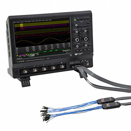
Introducing the Teledyne LeCroy HDO4104-MS High Definition, 1 GigaHertz bandwidth MSO with 4 analog channels. The display has an amazing resolution of 1280×800 pixels, with a color touch screen of 12.1 inches TFT LCD. The device has a three year warranty, included with an annual calibration. The product weighs 12.9 pounds with dimensions 291 height x 399 width x 131 depth (mm). The probes have a calibration output of 1 KiloHertz square wave, 1.0 V-p-p, output to probe hook. Detailed features and specifications are provided below.
Features/Specifications
| Model | Teledyne LeCroy HDO4104-MS |
|---|---|
| Bandwidth | 1 GigaHertz |
| Vertical System Bandwidth Limit | 20 MegaHertz |
| Record Length | Standard STD: 25MS - 16 Channels Optional -L: 50MS - 16 Channels |
| Channels | 4 |
| Input Impedance | 1 MegaOhm` |
| Input Coupling | 1 MΩ: AC, DC, GND; 50 Ω: DC, GND |
| Real time Sampling Rate | 450 ps |
| Trigger Modes | Auto, Normal, Single, Stop |
| Trigger Types | Edge, Glitch, Width, Logic (Pattern), TV (NTSC, PAL, SECAM, HDTV), Runt, Slew Rate, Interval, Dropout, Qualified |
| Trigger Source | CH1 - CH4, EXT, EXT/10, AC Line |
| Trigger Coupling Mode | AC, DC, LF Rej, HF Rej |
| Pre-trigger Delay - | (0-100)% Full Scale |
| Post-trigger Delay | (0-10,000) Divisions |
| Interpolation | Linear, (Sinx)/x |
| DC Gain Accuracy | (+/-) 0.5% Offset at 0 Volts |
| DC Gain Accuracy | (+/-) 0.5% Offset at 0 Volts |
| Timebase Range | 200 picoseconds/div to 1.25 kseconds/div |
| Horizontal System Clock Accuracy | +/-2.5ppm for 5 to 40C + 1.0ppm/year from calibration |
| Vertical Sensitivity | 2 millivolts to 5 volts/div |
| Vertical Resolution | 12 bits; up to 15 bits with enhanced resolution (ERES) |
| Mathematical Traces | 2 |
| Mathematical Operations | Add, SUB, MUL, DIV, FFT, Absolute Value, Averaging (summed and continuous), Derivative, Envelope, Enhanced Resolution, Floor, Integral, Invert, Reciprocal, Rescale, Roof, Square, Square Root, Trend, Zoom |
| Number of measurements displayed | 8 |
| Measurement Parameters | Amplitude, Area, Base, Delay, Delta Period @ Level, Delta Time @ Level, Duty Cycle, Duty @ Level, Edge @ Level, Fall Time (90% - 10%), Fall Time (80% - 20%), Frequency, Frequency @ Level, Maximum, Mean, Minimum, Overshoot+, Overshoot-, Period, Peak-Peak, Period, Period @ Level, Phase, Rise Time (10% - 90%), Rise Time (20% - 80%), RMS, Skew, Standard Deviation, Time @ Level, Top, Width+, Width- |
| Waveform Storage | 4 Waveforms |
| Interface | USB host (6 nos.) and device (1 no.), GBIP Port, Ethernet |
| Display | 12.1 inches, Color Touch Screen (1280x800) |
| Display Grid Styles | YT, XY |
| Power | 90 - 264) Volt AC, 45 HZ - 66 Hz || (90 - 132) Volt AC, 380 HZ - 420 Hz |
Another sizable industrial applications based mixed signal oscilloscope is the Keysight Technologies MSOX3104T Mixed Signal Oscilloscope: 1 GHz, 4 Analog Plus 16 Digital Channels. It is one of the most competitive product for the above reviewed Teledyne LeCroy model.
Digital Mixed Domain Oscilloscope (MDO)
A digital mixed domain oscilloscope is used to display signals in both the time and frequency domains. The use of time domain enables you to display digital waveforms, analog synchronized waveforms, and decoded serial protocols. For analyzing using the frequency domain an integrated spectrum analyzer signal path is added to the circuitry.
Most MDO’s used almost 16 channels for mixed signal debugging. Automated serial bus decoding and triggering can be carried out. The controls are simple and straightforward and are helpful in waveform navigation and search. Enough memory is provided for long recording. Versatile triggering can also be attained. The device also has a built-in spectrum analyzer and an arbitrary/function generator. Take a look at some of the best digital mixed domain oscilloscopes available in the market today.
Tektronix MDO3024, 200 MHz Mixed Domain Oscilloscope with 4 Channels
The Tektronix MDO3024 MDO includes many features like a 200 Mhz integrated spectrum analyzer, an arbitrary function generator, logic analyzer, protocol analyzer and digital voltmeter/counter. The oscilloscope has upgradeable features and is fully customizable. The device has a 5 digit DVM option enabled with post-purchase registration. Distinct feature like the Fast Acq Waveform Capture provides a waveform capture rate of 280,000 Wfm/s. This gives you a real idea of the waveform anomalies and its operation. Intensity grading options are also provided to indicate how often rare transients are occurring relative to normal signal characteristics. There are four waveform palettes available in FastAcq acquisition mode. They are the Temperature Palette, Spectral Palette, Normal Palette, and Inverted Palette that uses color-grading to indicate frequency of occurrence.
A complete set of triggers are provided by this model including more than 125 combinations. These triggers include runt, logic, pulse width/glitch, setup and hold violation, serial packet, and parallel data and many more. And with up to a 10 M record length, you can capture many events of interest, even thousands of serial packets, in a single acquisition for further analysis while maintaining high resolution to zoom in on fine signal details.
Advanced RF analysis, ultra-wide capture bandwidth, four different Spectrum traces, color-coded digital waveform display, MagniVu high-speed acquisition, remote connectivity, and standard Digital Voltmeter/Frequency Counter are among the additional features making the MDO3024 the integrated scope that maximizes test speed without sacrificing accuracy.
Features/Specifications
| Model | Tektronix MDO3024 |
|---|---|
| Bandwidth | 200 MegaHertz (Upgradeable to 1 GigaHertz) |
| Analog Channels | 4 |
| Sample Rate | 2.5 GS/s |
| Channel Length | 10 M |
| Maximum Waveform Capture Rate | Greater than 280,000 Wfm/s |
| Analog Bandwidth Range | GigaHertz, 500 MegaHertz, 250 MegaHertz |
| Display | 9 inch WVGA Wide Screen Color |
| Weight | 9.2 Pounds |
| Standard Frequency Range | 9 KiloHertz to Oscilloscope Bandwidth |
| Optional Frequency Range | 9 KiloHertz to 3 GigaHertz |
| Ultrawide Capture Bandwidth | Upto 3 GigaHertz |
| Automated Measurements and Waveform Histograms | 33 |
| Optional Functionalities | 50 MHz AFG, 121.2 ps Timing Resolution Logic Analyzer, Protocol Analyzer |
| Input Impedance | 101 KiloOhms |
| Serial Bus Supports | I2C, SPI, RS-232/422/485/UART, USB 2.0,CAN, LIN, FlexRay, MIL-STD-1553, and Audio standards |
The MDO3024 model oscilloscope uses a TekVPI probe interface probe that directly supports active, differential and current probes. Errors in signals and abnormal ones can be discovered in no time using FastAcq high-speed waveform capture rate feature. The output waveform signals can be easily sorted, searched and navigated using the waveform inspector controls. The device is in-built with 33 automated measurements and easy waveform analysis. The optional arbitrary function generator has 13 pre-defined waveform types with 50 MegaHertz waveform generation and with an arbitrary sample rate of 250 MS/s.
An optical protocol analyzer is also present with a serial bus support for I2C, SPI, RS-232/422/485/UART, USB 2.0,CAN, LIN, FlexRay, MIL-STD-1553, and Audio standards.
The front panel controls are provided for normally performed tasks. Automatic peak markers are provided to recognize frequency and amplitude spectrum peaks. Manual markers are also provided to measure the non-peak values. The types of traces provided re the Normal trace, Average trace, Maximum Hold trace, and Minimum Hold trace. The device is completely upgradeable for parameters like bandwidth increase and spectrum analyzer frequency range.
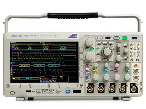
An upgraded version is the Tektronix MDO3104 1 GHz Mixed Domain Oscilloscope, 4 Analog Channels and 1 GHz Spectrum Analyzer. Check it out!!
Comments are closed.