Description.
Here is a simple but effective battery charger circuit using IC LM 317.The circuit can be used to charge 12Vlead acid batteries.The circuit is very simple and can be easily assembled on a general purpose PCB.
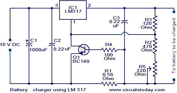
The heart of the circuit is IC LM 317 ,which is an adjustable voltage regulator IC.The pin 1 of the IC is the control pin which is used to control the charging voltage.The pin 2 is the output pin at which the charging voltage appears.The pin 3 is the input pin to which the regulated DC supply is given.
The charging voltage and current is controlled by the Transistor Q1,resistor R1 and POT R5.when the battery is first connected to the charging terminals ,the current through R1 increases.This in turn increases the current and voltage from LM 317.When the battery is fully charged the charger reduces the charging current and the battery will be charged in the trickle charging mode.
Circuit diagram with Parts list.
Notes.
- The input voltage to the circuit must be atleast 3V higher than the expected output voltage.LM 317 dissipates around 3V during its operation.Here I used 18V DC as the input.
- The charging voltage can be set by using the POT R5.
- The LM 317 must be mounted on a heat sink.
- All capacitors must be rated atleast 25V.
- You can use crocodile clips for connecting the battery to the charger.
53 Comments
can anyone make pcb board diagram for this circuit?
pls do or tell me how can i design a pcb board diagram for it.
Pls. , how could this circuit handle the required charging current (1/10Ahr) of car batteries?. LM317 could handle up to 1.5A only. Thanks in advance for your kind Reply.
Regards,
Tony
HI
to those that want more current, you could use a LM350 its like the 317 but 3A rated, but you are gone have to change the R1 Vbe=R1xI in tthis case (Vbe/I)=R1, knowing Vbe=0.65V and I= 3 R1=0.22Ohm now I²R1=P will give us power dissipated on R1 = 2W. The LM317/350 limits the max charging voltage and Q1 an R1 limit the current (Q1 use 30V rated and preferabli high Hfe). Once battery gets charged the current will drop and the voltage will increase and again will be limited bi R1 Q1 once the current is below 1 o3 A the voltage will increase to the max voltage set by VR5. You can put a load directly to the battery, but if you plan tou use it like an UPS, after a long power failure, voltage will fall nearly to 10V inclusive after power is reestablished. Adding another regulator and some diodes you could have an UPS, on mains while power ok and on battery on mains failure. But I think it’s not worth complicating the circuit if you use a 12 V 7Ah battery for a cordless phone or something like that. Great circuit
sir pls explain the operation…
hw i can see the battery is charging….
Sir,
I have a few clarifications about the schematics:
1. How to set the batteries charging current? what will be the default value of charging current set by the circuit that you have shared here.
2. Please explain me the operation of the transistor in this circuit and jow trickle charging is achieved.
Thanks in advance,
Rgds,
Kumar.
P.S. : I’am new to the field of electronics, you explanations would be off great valued to me.
sir, i have tried the circuit to charge 10ah Lead acid battery, but the current just 400mA. when i connect to load, the current is decrease.
how i can increase current rate for this circuit?? i charge the battery and supply the load in the same time. can i use BD135 to replace BC140?? because i can’t find the component.
thanks
sir,
what is the effect of potential divider r2 r3 r5 on working of transistor.
plz explain.
thank u
how will the output look on the CRO can i demonstrate the working without a battery please give me a detaild working of this circut
Sir, is this charger automatically stops after battery is charged fully? Where i can put led to have visible notification that the battery charged fully?
Thank you Seetharaman. How can i check if the device is working, it has a voltage output of 12v but im not sure if it is charging my battery. Thank you.
Hi Jhames IC1 is as a current limited voltage regulator. R1, R4 and Q1 are the current limiting circuit. R3 R2 R5 regulates the output(charging) voltage. For Q1 to conduct and stop the current from raising further the Vbe of voltage requirement for Q1 is 0.65 volts. The drop across R1 0.56 ohms will reach 0.65 volts, once the battery current reaches 0.65 / 0.56 = 1.15amps approx.
Thank You Seetharaman for that. With your help I was able to build it in my breadboard. Though I have one question more, what is the Ampere Rating of the output of the device? If I’am not mistaken it’s output is atleast 10mA. Doesn’t 12V lead acid batteries need atleast 1A? I hope you don’t mind. Thank you again.
Hi Jhames you can use BC639 or any small signal NPN transistor like bc148,bc147 2N2221, 2222, 8050, 2N1711, 2N2219, 2220. Here the voltage requirement is 24volt and a Ic of 10mA is more than sufficient.
I think BC140 is not available in our country, is it possible to use other transistors which are also NPN medium power transistor – BC639 for example, what parameter of the transistor do i have to take note? THANK YOU!
Can I use BC141 instead of BC140? Also, how can I produce 18Vdc, do I only need to apply a bridge rectifier? Thank you!
Dear MR.Seetharaman,
i am having confusion in battery charging voltage , some of the websites are saying 13.8 voltage is the maximum voltage for the battery charging , and in some of the websites 14.1,14.8 V are mentioned for 12V SMF batteries , so what is the exact max voltage that i can charge the battery
Thanking you
Athish
Dear Mr. Seetharaman,
I want to charge 12 V ,7 AH Battery with constant current of 800 mA and if battery reaches the setted voltage 13.8V DC, then the constant current charging should be disconnected and battery should be charged by constant voltage method , wether this circuit will deliver the same or i have to modify some thing in this and in this how can i set the current limit and voltage limit.( means that which resistanace i have to change to set the current and voltage is Pot R5 will be for both current and voltage or only current) kindly explain me
I wish to use this circuit for charging 10 nos, 7Ah SMF batteries at a time, connected in parallel.
I hv come across a circuit having 10 nos. LM317 mounted on heat sink having same control circuit to supply charging voltage
Any comment on this to make it successful
Hi Satyaranjan Q1 is for limiting the charging current once its be voltage is >0.65 volts it will conduct and the IC output will fall down. To calculate the current at wich it will limit with R1 = 0.65 / amps required
Sir how can I vary the current to 1.5A and why we are using transistor at the adjust terminal.Please reply.
Hi Satyaranjan this is a regulated voltage with current limitting charger, which will suit only Lead Acid Batteries requirement. You may check up the charger lable and adjust the output voltage to that value and set the current limit to 300 to 400mA.
Can I use it for nokia 5130 Xpress music phone ?if no then why?
Sir how the charging voltage and current is controlled by the Transistor Q1,resistor R1 and POT R5.Please explain this using suitable formula.If I donot use the transistor then what will happen.
Hi Pavan you are correct R2 should be 1.2K, the value shown is for 6volt lead acid battery.
this circuit provides max of 10.5 v only. correction is required in the value of r5 to get 14.3 v as output
Hi Vikram With 18 volt input you can charge a 12volt Leads Acid Battery.
This circuit cannot safely charge any other battery other than Lead Acid Battery.
Hi Emma You can increase amp rating of the charger such that it can charge as well supply the load requirement. (which is called float charging of the battery)
Thank you for the circuit. i want to know how i can modify this circuit so that the battery can be charging while powering a load at the same time.
what is the maximum output voltage the circuit can prodive?
I’m student,i need your assistance by sending all the information materials i need for my project topic which Design and construction of an Automatic 12V car battery charger with a digital voltmeter display to me.your website is best website for all learners.
is it that we can use only acid lead batteries to charge? can we put like the mobile battery of 3.7 volts?
Hi Edgardo the aove circuit can be used with little modification. Raise R2 to 1.8K R5 to 470 ohms and raise the input voltage to 28to 30volt DC. Use a good heat sink for LM317.
Hi Anuj The above circuit can be used with modifications, kindly give the specification of your battery for the solution.
can i charge the 3v battery from the 9v battery.
Hi Seetharaman, Good day..
Can there be a circuit for a battery charger using LM317 by 24 volts lead acid batteries?
Thanks.
Edgardo
Hi NFERMITO the current is limited to 1.1amp (the ICs current limiting factor is 1.5amps even without external limiting circuit) hence the wattage dissipation is just 0.35watts with 1.1amp, hence 1/2 watt is sufficient at the most you can use 1watt resistance.
R1 is 5W according to another internet site. Take care of it.
Hi, am a student who needs help on is project to Design a constant power battery charger with inherent soft-switching.
Hi Lao without battery set the output voltage at 13.8volt with pot for 12 volt battery for normal charge. set the voltage at 14.5 volt for boost charge. as the terminal voltage trying to reach the set voltage the charging current will fall down automatically. this setting will suit only 12volt lead acid batteries.
Hi, how can i set the set current? how can i control the current during charging and fully charge?
Hi Gan initially the battery will be on constant cuurrent mode and then bellow the set current mode will be charged on constant voltage mode. once the terminal voltages starts falling down due to self discharge of the battery the charger will start topping up the battery till such time its terminal voltage reaches the preset voltage. the process continues.
Hi,
I just want to confirm that which component will trigger the trickle charging mode? Is it because of the transistor is experiencing cut off then the battery will no longer be charged?
Hi,
I am charging a 7AH-12v lead-acid bat with a solar cell and not using the transistor and the R1(.56 Ohm).(i.e. using only LM317 and two register to set the o/p voltage to 14.4v in no-load condition). My question is why we need the R1 ?
Thanks,
Sanjib
I’m student,i need your assistance by sending all the information materials i need for my project topic which Design and construction of an Automatic 12V car battery charger with a digital voltmeter display to me.your website is best website for all learners.
I HAVE LOST MY CAR CENTRAL LOCKING REMOTE,IS THEIR ANY CIRCUIT TO UNLOCK IT.BEFORE SOMEONES TRIES TO STEAL IT.
PLZZZZZZZZZZZZZZZZZZZZZZZZZZZZZZZZZZZZZZZZZZZZZZZZHELP ME…
pls help me with a single phase automatic change over switch circuit diagram & the full write up,pls it’s algent,i need it 4 a project.2 my e-mail aaabdul86@yahoo.com
pls help me with a single phase automatic change over switch circuit diagram & the full write up,pls it’s algent,i need it 4 a project
http://forum.allaboutcircuits.com/showthread.php?t=23063
i want to increase charging current to 120 ma pls tell me the modification
Solution: Put a diode at the positive pole just before the battery connection.
LM 317 can be used for charging SMF batteries
I want to make a Exit light,but i face a problem from a 6V batery charge and also i want to exit light all time lighting by ac 220v to dc adapter from bc and battery charge but when ac is off then battery backup and led light is lighting.please circuit diagram solve
I have some questions:
Is there any problem if I use LM317-Charger circuit for charging Sealed Lead Acid batteries?
BC140 is not available, what are the replacements I can use?
Thanks
BD139 should work fine
The LM 317 is rated at 1.5A max. Multiply this by 10 for a/h rating of the battery, so max battery size is around 14a/h.