Auto Intensity Control Of Street Light Using Arduino
In this project, I am going to show you how to control the intensity of LED lights according to the time and the light intensity of outer atmosphere.
This is an amazing and very useful project because it prevents the wastage of electricity.
This project automatically turns on the streetlight at evening and turns off in the morning. It also controls the intensity of light. Light intensity is automatically adjusted according to the time and traffic. The number of vehicles is very low after 12AM. For example, the intensity of light is low in the evening and it starts increasing until 8PM After 8PM the light glows at full intensity and this intensity will not change. It glows on full intensity until 12AM and intensity starts decreasing after 12AM, and the lights are fully turned off after 6AM. This approach saves about 30 percentage energy.
In the circuit two LEDs are also used, one is Green and other is Red. The Red LED indicates the evening and the Green Led indicates midnight time 12AM. The Arduino is not programmed for the real time, because we cannot observe the changes in live. Therefore, time delay is very low (1hr is equal to 3 second). You can change the time delay according to your use. You can make many modifications in the project according to your use, you can also use RTC (Real Time Clock) in this project.
Working
In the circuit a LDR (Light Dependent Resistor) is used, which detect the intensity of the lights, when the intensity of light comes under a fixed values the led Light is turn ON. But at the starting intensity of the light is low because the time is 5PM. Now the intensity is increasing with the time and light glows on full intensity at 8 PM.

Intensity of the light is controlled by using PWM (pulse width modulation). The Arduino and other digital devices cannot give analog output; they can only give the digital output (High or Low). Means they can only turn OFF and turn ON the device, but sometimes we need the voltage between Vcc and GND. PWM can fulfill this requirement. PWM simply Turn On and Turn Off the output device at the high frequency. In this way the output voltage becomes under Vcc. Value of the output voltage depends upon “Turn On” time and “Turn Off” time, which can be calculated by the given function below
Duty Cycle = Ton / (Ton + Toff)

Vout = Duty Cycle * Vcc
The Arduino Nano have six PWM pins, they all are 8 bit. In other words, we can change the output value from 0 to 255 where 0 is low and 255 is High.
Two LEDs are also used on Circuit, they indicates the time, RED LED turns on when LDR cross the threshold value, in my case I suppose time is 5 PM, at this time our street light (power LED) also switched on but the intensity is low. The intensity is gradually increasing and it will works on full intensity at 8 PM. Now the intensity is not changed until 12 am.
After 12 AM, the Green LED is turned on and the power LED’s intensity become low this intensity is not changed until 4 AM. After 4AM, the intensity of the light starts gradually decreasing. In addition, it becomes fully turn off at 6 AM.
Components
| Components | Specifications | Quantity |
|---|---|---|
| Arduino | Nano | 1 |
| Power Source | DC Adapter 12 volt | 1 |
| LDR (Light Dependent Resistor) | 1 | |
| LED | Green, Red | 2 |
| Power LED | 12 Volt | 1 |
| Transistor | BC 547 | 1 |
| Resistor | 330 Ohm | 2 |
| Resistor | 10K | 1 |
| Resistor | 1K | 1 |
| Diode | 1N4007/ 1N4004 | 1 |
Circuit
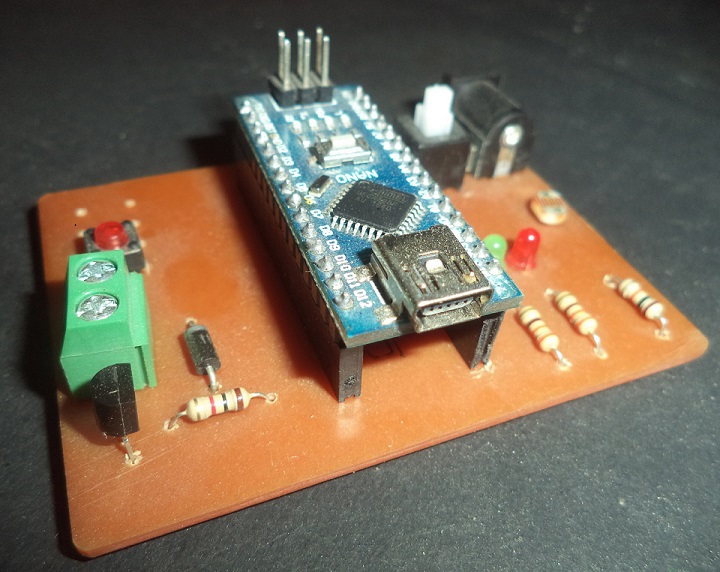
The circuit is very simple, you can make this circuit on breaboard or ZERO PCB using the circuit below.
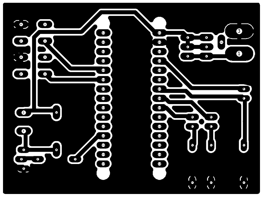
If you are good in the PCB Etching use the images given below.
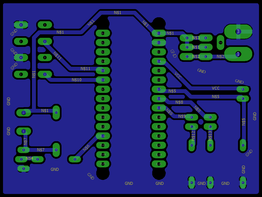
In the circuit Arduino Nano is used, PWM pin D9 is connected to the base pin of the transistor (2N2222) emitter pin is connected to the GND. Power LED’s Cathode pin is connected to the Collector pin of the transistor and the anode pin is connected to 12-volt, A diode is connected parallel to the Power LED in the reverse bias.
The LDR is connected to the Vcc and the GND through a resistance of 10k ohm, junction point of LDR and Resistance is connected to the A5 pin of the Arduino.
Two LEDs are connected to the A4 and A3 pin of the Arduino through 330 ohm Resistance. Circuit is powered by 12 volt adapter and 12 volt line is also connected to the Vin pin of the Arduino through a Switch.
Auto Intensity Control of Street Light – Video
Code
In the code some integers are declared, integer “sensor” is used for the LDR pin, LED1 and LED2 are used for the “RED”, and “GREEN” LED, And the integer “OUT” is declared for the Power LED. Integer “del” is used for giving the delay of 1 hr (3 sec).
In the “void setup ()” sensor is declared as INPUT and LED1, LED2 and OUT are declared as OUTPUT, using “pinMode” function.
In the “void loop()” first an “if condition” is used for comparing the value for the LDR sensor, when “analogRead” value of LDR sensor is less than 50 “if condition” become true.
Next “analogWrite(LED1,100)” switch on the Power LED at low the intensity. LED1 is also switched on using “digitalwrite(LED1, HIGH)” and delay is given for “del” time.
After it, some functions are used for changing the intensity of Power LED after every one hr (delay of 3000ms). At 12AM the LED2 (Green LED) is also switched on, at the ending of the code LED1 and LED2 are switched off.
Calibration: calibration is used for turn of the light at right time, in the line 20 change the value compared “analogRead(sensor)”, in the given code it is 50, you can read the value using “AnalogReadSerial” in the example.
6 Comments
I make this project for my final year project. Please help me total circuit diagram and simulation circuit. And programing code and which software is use for simulation. Please reply me .it is help to me.i am in trouble to making this project …AUTO INTENSITY CONTROL BY USING ARDINO
Hi
I really want to know that what’s connected to the d2 and d3 pins?
Please someone answer me…
Hi,
Thanks for this great project.
I have to make this project and i need so much help, how can i find the schematic circuit of this project? Can you please help me??
Hello good time
What is the length and width of copper fiber?
Please i would like you to help me with circuit diagram , my project has to do with auto intensity street lighting for residential compound not outdoor traffic. I want to light to come on once it is 7pm ,then intensity starts dropping from 1AM and go off finally at 6:30AM. Am thinking of programming it to the right time not , and am also powering it using a solar & generator supply as back up incase sunlight fails? I need circuit diagrams and few other things
dear sir
I am kaluya moses from uganda, a hobbies t of electronics i have some experience in circuit building
I have done this for some time, Now I need to do earning projects like this one.
So, AUTO INTENSITY CONTROL OF STREET LIGHT l have liked it therefore l want to try it by means of your help and, eventually we might do other things
Sir, since l don’t have Arduino nano what is the equivalency ic to be used?
thanks.