An introduction to Audio Oscillators also known as RC Oscillators
So far, we have considered the oscillators which use L-C tuned circuit that causes a phase shift of 180° due to inductive or capacitive coupling in addition to a 180° phase shift produced by the transistor itself. The oscillators employing L-C elements, called the L-C oscillators, are very popular for generating high frequency oscillations but they cannot be employed for generation of low frequency oscillations as they become too bulky and expensive. R- C oscillators are commonly used for generating audio-frequencies as they provide good frequency stability and waveform. Also, with the advent of IC technology, R-C network is the only feasible solution, as it is very difficult to make a too high value inductance in an integrated circuit. Two commonly used R-C oscillators are (i) R-C phase shift oscillator and (ii) Wien bridge oscillator. Another commonly used audio-oscillator is the beat frequency oscillator (BFO). So these three audio-oscillators will be discussed here.
Basic Principles of R-C Oscillators.
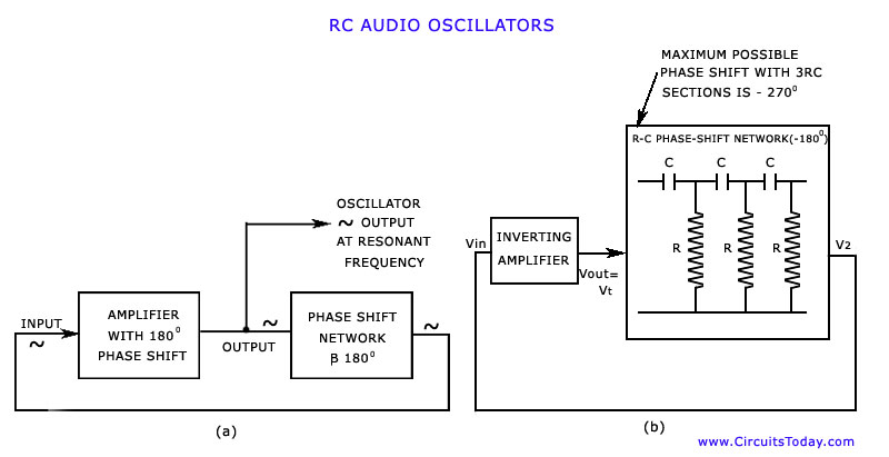
For producing oscillations in an oscillator circuit we need positive feedback which means that the voltage signal feedback should be in phase with the input signal. For providing a positive feedback at one particular frequency, an inverting amplifier may be used with a feedback network that causes a phase shift of 180° at the desired frequency of oscillation, as shown in fig. (a). The 180° phase shift in the feedback signal can be obtained by a suitable network consisting of three R-C sections, as shown in fig. (b).
When a phase-shift network such as that indicated in fig. is used in a phase shift oscillator, the R’s and C’s must be selected so as to produce a phase shift of 180° at the desired frequency of oscillation. The output of the voltage amplifier is fed to the input to the phase-shift network. Thus V1 = Vout. The output resistance of the amplifier is designed to be very small in comparison to the input impedance of the phase-shift network. The output voltage of the phase-shift network, V2 is fed into the input of the amplifier i.e., V2 = Vin. The amplifier’s input impedance must be much larger than the output impedance of the phase-shift network.
Alternatively, a positive feedback can be obtained by using two stages of amplifiers each giving a phase shift of 180°. A part of this output is fedback to the input through a feedback network without causing any further phase shift. Wien bridge oscillator operates on this principle.


1 Comment
thanks for your efforts that has helps us to find what we need for the good of our academic progress.