Description.
This circuit can be used to identify whether there is a clipping in a particular wave form. Clipping is a phenomenon in which the amplitude of a particular waveform drops before it reaches the expected limit. This circuit glows an LED as an indication if the signal under test has clipping. The circuit is very useful in sorting out distortion problems in amplifiers.
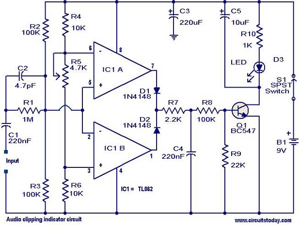
The circuit is based on a window comparator based on the two opamps inside the IC1 (TL082).The circuit detects the positive or negative peak value reached by the input signal. The output of the opamp is combined by the two diodes D1 & D2 and drives the transistor Q1 to glow the LED. The capacitor C5 is employed to induce a small time delay in order to detect very fast and short peaks. The POT R1 can be used to set the level of clipping at which the LED has to glow. The circuit can be used with almost all sorts of mixers, power amplifiers and preamplifiers.
Circuit diagram with Parts list.
Notes.
- Assemble the circuit on a good quality PCB or common board.
- The circuit can be powered from a 9V PP3 battery.
- The POT R5 can be use to calibrate the circuit.
- The IC1 must be mounted on a holder.
Comments are closed.