Arduino Gear Motor Interface Using IC L293D
In this article, we are publishing a project which explains different aspects of Arduino-Gear motor interface. Gear motor is a specially designed DC motor whose gear assembly helps in increasing the torque and reducing the speed. Compared to a normal DC motor, maximum rpm a gear motor can produce is less. But they have the advantage that by using the correct combination of gears, its rpm can be reduced to any desirable value. Unlike servo motor, gear motor can also be rotated continuously. The direction of the gear motor can be reversed by simply reversing the polarity of the battery connection. And the speed of the motor can be controlled by changing the voltage level across it. A motor driver IC named L293D is used here for interfacing the gear motor with Arduino. L293D consist of two H-bridge designed using 4-transistor circuit that helps us to reverse the direction of rotation and to control the speed of the DC motor.
Let’s begin our tutorial and learn how IC L293D-Arduino-Gear motor interface is done.
Objectives of the Project
- Interfacing of gear motor with Arduino.
- Generating code for turning motor to a desired direction.
- Controlling the speed of motor using a potentiometer.
Components Required
| Component | Specification | Quantity |
|---|---|---|
| Arduino | Uno | 1 |
| Potentiometer | 10K | 1 |
| Motor Driver | L293D | 1 |
| Adapter | 9V, 1A | 1 |
| Geared DC Motor | (6-12)V | 1 |
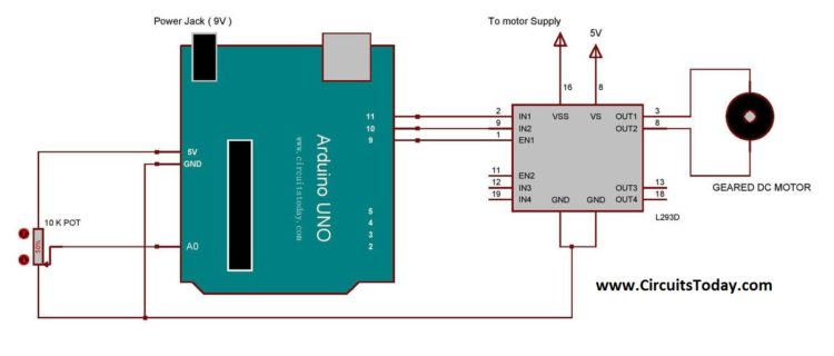
Circuit Diagram
Assemble the circuit as shown in the diagram. Component and connections are explained below.
Circuit Explanation
In the circuit an Arduino UNO is used as the platform. Gear Motor is connected to Arduino UNO via motor driver IC L293D. As mentioned earlier, a motor driver IC consists of two H-bridge circuits which can be used for controlling two motors simultaneously. An L293D has 4 input pins, 4 output pins, 2 enable pins, Vss, Vcc and GND. Vcc is the voltage that it needs for its internal operation. L293D will not use this voltage for driving the motor. For driving the motors it has a separate provision to provide motor supply Vss.
Here we are using only one DC motor, hence the first two input pins of the IC alone is used. These are connected to any two digital pins of Arduino (here they are, 10 & 11). And two output pins of L293D are connected to a gear motor. E1 pin (Enable Pin) of L293D is then connected to any of the PWM pin of Arduino (here it is 9th pin). We can simply run the motor by giving a high signal at 10th pin, low at 11th pin and a high at the enable pin. The 10th and 11th pin of Arduino is used for controlling the direction of rotation and the 9th pin is for regulating the speed of the motor. The speed regulation is achieved by generating a PWM signal at the enable pin of the L293D IC.
A potentiometer is used in this project for determining the strength of the PWM signal that is to be given at the enable pin. The output pin from the potentiometer is connected to A0 (analog pin) of Arduino. By varying the potentiometer, the voltage at the A0 pin will varies from 0 to 5V. This varying analog signal is them mapped to desired value and uses for generating PWM signal.
L293D Motor Driver-Arduino-Gear Motor Interface Video
The Program/Code
The important aspects and subroutines of the program are explained below.
At the beginning of the program, four preprocessors are defined which mention the Arduino pins which are use for interfacing. At the “setup()” function, the Arduino pins that are used for controlling the motor are configured as output pins. And the pin that is used for taking the analog reading from the potentiometer is configured as input pin.
At the “loop()” function, two variables are declared at the beginning. “analogRead()” is the function used for assigning values to the variable named “potValue”. “analogRead()” function reads the value from the specified analog pin. The Arduino board contains a 10-bit analog to digital converter. This means that it will map input voltages between 0 and 5 volts into integer values between 0 and 1023.
“analogWrite()” is used for generating desired PWM signal at a pin. The input parameters for this function are the pin number and the PWM value ( ranging between 0-254). Since the PWM value limit ends at 254, we need to map the variable “potValue” to appropriate range. “map()” is a function which re-maps a number from one range to another. The value thus obtained is then assigned to a variable named “pwmValue”. This is then used as parameter for “analogWrite()” function and generates the desired PWM signal.
Comments are closed.