In this article, we are publishing a tutorial on how to interface seven segment LED display to Arduino. Seven segment displays are used in many embedded system and industrial applications where the range of outputs to be shown is known beforehand. Basic 1 digit seven segment display can show numbers from 0-9 and a few characters. 7 segment displays are of different types; especially they differ in the number of digits/character it can display. Basically a 7 segment display is a single unit, which can display only 1 digit or 1 character. More digits are displayed by multiplexing single unit 7 segment displays together to form 2 digit display, 3 digit display or 4 digit 7 segment display. Its quiet easy to interface Arduino and 7 Segment display together! Lets begin the tutorial.
A 7 segment display has many limitations, especially in the range of characters it can display.There are displays in market which are much more advanced than seven segment displays and can display almost every character in the alphabet. For example:- a 16×2 LCD – which can display almost all ASCII characters. You might think why 7 segment display still exist in market. Well, 7 segment displays are the cheapest option when it comes to display devices available in market. A single digit/character 7 segment display unit is available at 1/10th of the cost of a 16×2 LCD module.
We begin this tutorial by interfacing a single digit (1 digit/character) 7 segment LED display to Arduino.Once we learn the single digit 7 segment display interfacing to arduino and its code/program, we move on to interface 4 digit seven segment display with arduino using shift register.
It is recommended study following areas of arduino prior to this article:
- How to install a library to arduino
- Arduino timer
- Shift Registers
- Arduino shiftOut
Let’s begin the tutorial. We are going to use Arduino uno and a basic seven segment display with decimal point. You can identify the segments of the display with the help of following figure.
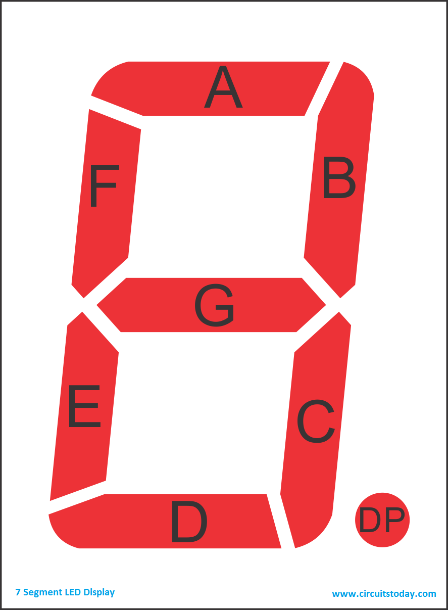
This seven segment display has a total of 8 LEDs per digit as shown in above image, seven LED’s for each segment and one for the decimal point. As mentioned above, we are using two types of seven segment displays in this tutorial -1) the single digit 7 segment display 2) the 4 digit 7 segment display and they both will be interfaced with arduino in two different ways.
Interfacing single digit seven segment display to Arduino
We are going to interface a seven segment display with single digit/character to arduino uno. Final result would be displaying 0-9 on the display. Lets identify the pinout and circuit diagram of the display.
Single Digit Seven Segment Display – Pin Out Diagram
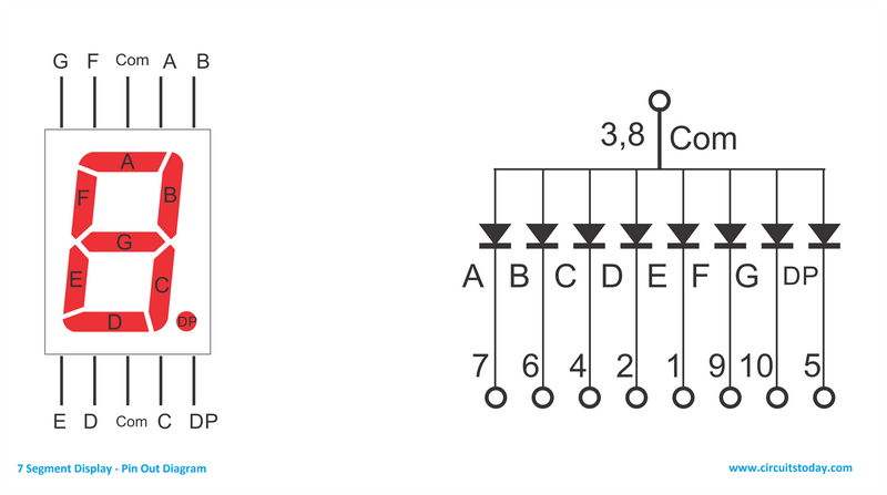
As you can see there are 10 pins in total. You may notice two pins named com, as shown in the circuit diagram all the anodes (+ pins) of the LEDs are connected to these two pins. We call these 2 pins as common anodes and such displays are called Common Anode 7 segment displays. There are some seven segment displays which have common cathodes instead of common anodes. The only difference for common cathode displays is all the cathodes (- pins) are connected together and they are known as Common Cathode 7 segment displays. Apart from these 2 com pins, there are 8 other pins named A,B,C,D,E,F,G and DP. As you can see in the figure, these pins are cathodes (- pins) of the led segments of common anode display (in the case of common cathode display these pins will be anodes)
To turn on each segment ( LED), we have to supply appropriate voltage to it. Lets just say we want to show number “3” on the display. To display ‘3’ properly, we need to turn ON A,B,C,D & G segment LED’s (refer the figures ). since anodes are common, we supply positive voltage to common anode pins and connect GND (ground) to the segment pins we want to turn ON. If you wire like this on a breadboard. the 7 segment display will show ‘3’ on its display. But hard wiring is not practical, as we need to change the wiring all the time we want to change digit/character to be displayed. We use micro controllers like 8051 or AVR or even Arduino to solve this problem. We can manipulate the 7 segment wiring (the process of turning ON and OFF led segments) using software inside the micro controller. In our tutorial of interfacing with arduino, we achieve this by writing specific lines of arduino code to turn led segments ON and OFF
Circuit Diagram – 7 Segment Display to Arduino
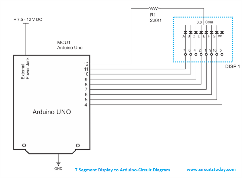
Each segment of the display is connected to a digital pin of arduino as shown in the circuit diagram. Two common pins are connected to the arduino digital pin 12 through a 220Ω resistor. This 220 ohms resistor is used as a current limiting resistor to limit the current passing through the led’s and hence prevent any damage to the led segments and the arduino itself.
Arduino Code for Interfacing Single Digit 7 Segment Display to Arduino
Use following arduino code for the common anode 7 segment display
int seg_a = 11; // declare the variables
int seg_b = 10;
int seg_c = 9;
int seg_d = 8;
int seg_e = 7;
int seg_f = 6;
int seg_g = 5;
int seg_dp = 4;
int com = 12;

void setup() {
  pinMode(seg_a,OUTPUT); // configure all pins used to outputs
  pinMode(seg_b,OUTPUT);
  pinMode(seg_c,OUTPUT);
  pinMode(seg_d,OUTPUT);
  pinMode(seg_e,OUTPUT);
  pinMode(seg_f,OUTPUT);
  pinMode(seg_g,OUTPUT);
  pinMode(seg_dp,OUTPUT);
  pinMode(com,OUTPUT);

}

void loop() {
digitalWrite(com,HIGH); // set common anode HIGH (5V)
for (int i = 0; i < 10; i++) { // count 0 - 9
 switch(i){ // switch statemet to select the number

  case 0: // set relevent segments HIGH and others LOW
  digitalWrite(seg_a,LOW);
  digitalWrite(seg_b,LOW);
  digitalWrite(seg_c,LOW);
  digitalWrite(seg_d,LOW);
  digitalWrite(seg_e,LOW);
  digitalWrite(seg_f,LOW);
  digitalWrite(seg_g,HIGH);
  digitalWrite(seg_dp,HIGH);
  break;

  case 1:
  digitalWrite(seg_a,HIGH);
  digitalWrite(seg_b,LOW);
  digitalWrite(seg_c,LOW);
  digitalWrite(seg_d,HIGH);
  digitalWrite(seg_e,HIGH);
  digitalWrite(seg_f,HIGH);
  digitalWrite(seg_g,HIGH);
  digitalWrite(seg_dp,HIGH);
  break;

  case 2:
  digitalWrite(seg_a,LOW);
  digitalWrite(seg_b,LOW);
  digitalWrite(seg_c,HIGH);
  digitalWrite(seg_d,LOW);
  digitalWrite(seg_e,LOW);
  digitalWrite(seg_f,HIGH);
  digitalWrite(seg_g,LOW);
  digitalWrite(seg_dp,HIGH);
  break;

  case 3:
  digitalWrite(seg_a,LOW);
  digitalWrite(seg_b,LOW);
  digitalWrite(seg_c,LOW);
  digitalWrite(seg_d,LOW);
  digitalWrite(seg_e,HIGH);
  digitalWrite(seg_f,HIGH);
  digitalWrite(seg_g,LOW);
  digitalWrite(seg_dp,HIGH);
  break;

  case 4:
  digitalWrite(seg_a,HIGH);
  digitalWrite(seg_b,LOW);
  digitalWrite(seg_c,LOW);
  digitalWrite(seg_d,HIGH);
  digitalWrite(seg_e,HIGH);
  digitalWrite(seg_f,LOW);
  digitalWrite(seg_g,LOW);
  digitalWrite(seg_dp,HIGH);
  break;

  case 5:
  digitalWrite(seg_a,LOW);
  digitalWrite(seg_b,HIGH);
  digitalWrite(seg_c,LOW);
  digitalWrite(seg_d,LOW);
  digitalWrite(seg_e,HIGH);
  digitalWrite(seg_f,LOW);
  digitalWrite(seg_g,LOW);
  digitalWrite(seg_dp,HIGH);
  break;

  case 6:
  digitalWrite(seg_a,LOW);
  digitalWrite(seg_b,HIGH);
  digitalWrite(seg_c,LOW);
  digitalWrite(seg_d,LOW);
  digitalWrite(seg_e,LOW);
  digitalWrite(seg_f,LOW);
  digitalWrite(seg_g,LOW);
  digitalWrite(seg_dp,HIGH);
  break;

  case 7:
  digitalWrite(seg_a,LOW);
  digitalWrite(seg_b,LOW);
  digitalWrite(seg_c,LOW);
  digitalWrite(seg_d,HIGH);
  digitalWrite(seg_e,HIGH);
  digitalWrite(seg_f,HIGH);
  digitalWrite(seg_g,HIGH);
  digitalWrite(seg_dp,HIGH);
  break;

  case 8:
  digitalWrite(seg_a,LOW);
  digitalWrite(seg_b,LOW);
  digitalWrite(seg_c,LOW);
  digitalWrite(seg_d,LOW);
  digitalWrite(seg_e,LOW);
  digitalWrite(seg_f,LOW);
  digitalWrite(seg_g,LOW);
  digitalWrite(seg_dp,HIGH);
  break;

  case 9:
  digitalWrite(seg_a,LOW);
  digitalWrite(seg_b,LOW);
  digitalWrite(seg_c,LOW);
  digitalWrite(seg_d,LOW);
  digitalWrite(seg_e,HIGH);
  digitalWrite(seg_f,LOW);
  digitalWrite(seg_g,LOW);
  digitalWrite(seg_dp,HIGH);
  break;

 }
  delay(1000); // Show each number for 1 second
  }

}
Use following arduino code for the common cathode 7 segment display
int seg_a = 11; // declare the variables
int seg_b = 10;
int seg_c = 9;
int seg_d = 8;
int seg_e = 7;
int seg_f = 6;
int seg_g = 5;
int seg_dp = 4;
int com = 12;

void setup() {
  pinMode(seg_a,OUTPUT); // configure all pins used to outputs
  pinMode(seg_b,OUTPUT);
  pinMode(seg_c,OUTPUT);
  pinMode(seg_d,OUTPUT);
  pinMode(seg_e,OUTPUT);
  pinMode(seg_f,OUTPUT);
  pinMode(seg_g,OUTPUT);
  pinMode(seg_dp,OUTPUT);
  pinMode(com,OUTPUT);


}

void loop() {
digitalWrite(com,LOW); // set common anode HIGH (5V)
for (int i = 0; i < 10; i++) { // count 0 - 9
 switch(i){ // switch statemet to select the number

  case 0: // set relevent segments HIGH and others LOW
  digitalWrite(seg_a,HIGH);
  digitalWrite(seg_b,HIGH);
  digitalWrite(seg_c,HIGH);
  digitalWrite(seg_d,HIGH);
  digitalWrite(seg_e,HIGH);
  digitalWrite(seg_f,HIGH);
  digitalWrite(seg_g,LOW);
  digitalWrite(seg_dp,LOW);
  break;

  case 1:
  digitalWrite(seg_a,LOW);
  digitalWrite(seg_b,HIGH);
  digitalWrite(seg_c,HIGH);
  digitalWrite(seg_d,LOW);
  digitalWrite(seg_e,LOW);
  digitalWrite(seg_f,LOW);
  digitalWrite(seg_g,LOW);
  digitalWrite(seg_dp,LOW);
  break;

  case 2:
  digitalWrite(seg_a,HIGH);
  digitalWrite(seg_b,HIGH);
  digitalWrite(seg_c,LOW);
  digitalWrite(seg_d,HIGH);
  digitalWrite(seg_e,HIGH);
  digitalWrite(seg_f,LOW);
  digitalWrite(seg_g,HIGH);
  digitalWrite(seg_dp,LOW);
  break;

  case 3:
  digitalWrite(seg_a,HIGH);
  digitalWrite(seg_b,HIGH);
  digitalWrite(seg_c,HIGH);
  digitalWrite(seg_d,HIGH);
  digitalWrite(seg_e,LOW);
  digitalWrite(seg_f,LOW);
  digitalWrite(seg_g,HIGH);
  digitalWrite(seg_dp,LOW);
  break;

  case 4:
  digitalWrite(seg_a,LOW);
  digitalWrite(seg_b,HIGH);
  digitalWrite(seg_c,HIGH);
  digitalWrite(seg_d,LOW);
  digitalWrite(seg_e,LOW);
  digitalWrite(seg_f,HIGH);
  digitalWrite(seg_g,HIGH);
  digitalWrite(seg_dp,LOW);
  break;

  case 5:
  digitalWrite(seg_a,HIGH);
  digitalWrite(seg_b,LOW);
  digitalWrite(seg_c,HIGH);
  digitalWrite(seg_d,HIGH);
  digitalWrite(seg_e,LOW);
  digitalWrite(seg_f,HIGH);
  digitalWrite(seg_g,HIGH);
  digitalWrite(seg_dp,LOW);
  break;

  case 6:
  digitalWrite(seg_a,HIGH);
  digitalWrite(seg_b,LOW);
  digitalWrite(seg_c,HIGH);
  digitalWrite(seg_d,HIGH);
  digitalWrite(seg_e,HIGH);
  digitalWrite(seg_f,HIGH);
  digitalWrite(seg_g,HIGH);
  digitalWrite(seg_dp,LOW);
  break;

  case 7:
  digitalWrite(seg_a,HIGH);
  digitalWrite(seg_b,HIGH);
  digitalWrite(seg_c,HIGH);
  digitalWrite(seg_d,LOW);
  digitalWrite(seg_e,LOW);
  digitalWrite(seg_f,LOW);
  digitalWrite(seg_g,LOW);
  digitalWrite(seg_dp,LOW);
  break;

  case 8:
  digitalWrite(seg_a,HIGH);
  digitalWrite(seg_b,HIGH);
  digitalWrite(seg_c,HIGH);
  digitalWrite(seg_d,HIGH);
  digitalWrite(seg_e,HIGH);
  digitalWrite(seg_f,HIGH);
  digitalWrite(seg_g,HIGH);
  digitalWrite(seg_dp,LOW);
  break;

  case 9:
  digitalWrite(seg_a,HIGH);
  digitalWrite(seg_b,HIGH);
  digitalWrite(seg_c,HIGH);
  digitalWrite(seg_d,HIGH);
  digitalWrite(seg_e,LOW);
  digitalWrite(seg_f,HIGH);
  digitalWrite(seg_g,HIGH);
  digitalWrite(seg_dp,LOW);
  break;

 }
  delay(1000); // Show each number for 1 second
  }

}
Program Explanation.
The arduino code given above is very simple and follows the beginners approach. Same program can be written in lesser number of lines using arrays and other advanced programming elements. In first few lines we have assigned the segment names to the arduino pins. And in the setup we have configured every pin we are going to use as outputs. In the loop, a for loop is used to count 0-9 and switch statement is used to select the relevant set of statements to show the desired output.
Results
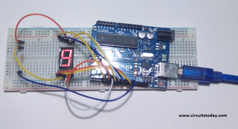
Fallowing image shows the actual setup of the above circuit on a breadboard and the final results
Interfacing four digit seven segment display to Arduino
Now we are going to see how to interface 4 digit 7 segment display with arduino. We are going to use a different method to control this Four digit display. Let’s see the pinout of this 4 digit 7 segment display.
Pin Out – 4 Digit 7 Segment Display
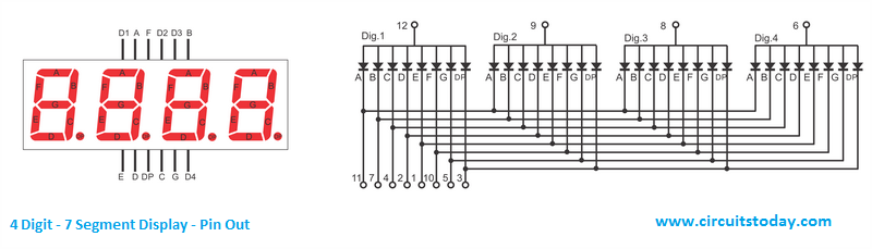
As you can see in this pin out diagram of 4 digit 7 segment led display, there are a total of 32 led segments. But as you can see there are only 12 pins. As shown in the circuit diagram there are 4 common anodes and also cathodes of same segments are connected together. So if we connect all the segment pins to negative (ground) and common pins to positive, you can see all the segments of all four digits are turned on. By switching between the four common anodes we can choose which display to turn on. But as you can see we can’t display four different digits the same time in this display as cathodes are same for all four digits.
Multiplexing Technique
So how we are going to display a number like 1234 on this 4 digit display? For this we are going to use a method called multiplexing. What multiplexing does is simple – show one digit at a time on a display unit and switch between display units very fast. Due to persistence of vision, human eye can not differentiate between which display is ON/OFF. The human eye just visualizes all the 4 display units to be ON all the time. Let’s say we need to show 1234. First we turn on the segments relevant to “1” and turn on the 1st display unit. Then we send signals to show “2”, turn off 1st display unit and turn on 2nd display unit. We repeat this process for next two numbers and switching between display units should be done very fast (about within one second delay). As our eyes can’t pick a change occurring repeatedly to any object within 1 second, what we see is 1234 appearing on the display at the same time.
Circuit Diagram – Interfacing Arduino to 4 Digit 7 Segment Display using Shift Register
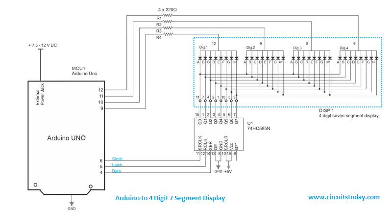
As you can see in the diagram we are using an IC named 74HC595N in addition to arduino uno and 4 digit seven segment display. 74HC595N – is a shift register IC and it converts serial data to parallel data. This shift register IC is used to reduce the number of digital I/O pins of arduino required to control the 7 segment display. As obvious from the circuit diagram, we need only 3 arduino digital pins (connected to shift register IC) to control 8 segment lines of 4 digit seven segment display.
Name of the pins and their functions of shift register 74HC595N are mentioned below:
- Q0 – Q7 – Parallel Data output
- SRCLK – Shift Register Clock Input pin, a clock pulse should be send to this pin from arduino. If not shift register can’t identify the starting and end points of the data
- RCLK – Storage clock also known as the Latch pin, this pin is used to set the mode of shift register. When latch pin is set to LOW shift register reads input values.
- OE – Output Enable, this pin should be connected to ground for the shift register to output values.
- SRCLR – Shift Register Clear – when this pin is connected to Vcc, all the data stored in shift register will be cleared
- SER – Serial data input
- Q7” – Serial data output. This pin outputs serial data given to SER pin. Normally used to connect another shift register – i.e cascading of shift registers.
All the segments of 7 segment display are connected to the parallel data output pins of the shift register. Clock, latch and serial data pins of the shift register are connected to arduino digital pins 6,5 & 4 respectively. Each of the four common anode pins are connected to a unique arduino pin (9,10,11 and 12) through a 220Ω resistor to limit the current.
Arduino Code – for interfacing 4 digit 7 segment display to arduino using shift register
Use following code for the common anode 7 segment display.
#include "Timer.h" //include timer library


Timer t; // craete a timer object
long number = 0; //declear the variables
int first_digit = 0;
int second_digit = 0;
int third_digit = 0;
int fourth_digit = 0;
int timer_event = 0;
int CA_1 = 12;
int CA_2 = 11;
int CA_3 = 10;
int CA_4 = 9;
int clk = 6;
int latch = 5;
int data = 4;
int count = 0;
int digits[4] ;
int CAS[4] = {12, 11, 10, 9};
byte numbers[10] {B00000011, B10011111, B00100101, B00001101, B10011001, B01001001, B01000001, B00011111, B00000001, B00001001};
//byte combinations for each number 0-9
void setup() {
  Serial.begin(9600); //serial start and pin config
  pinMode(CA_1, OUTPUT);
  pinMode(CA_2, OUTPUT);
  pinMode(CA_3, OUTPUT);
  pinMode(CA_4, OUTPUT);
  pinMode(clk, OUTPUT);
  pinMode(latch, OUTPUT);
  pinMode(data, OUTPUT);
  digitalWrite(CA_1, LOW);
  digitalWrite(CA_2, LOW);
  digitalWrite(CA_3, LOW);
  digitalWrite(CA_4, LOW);
  Serial.println("please Enter a number from 0 to 9999");
}

void loop() {
  t.update(); //timer update
  if (Serial.available()) { // read from serial
    t.stop(timer_event); //stop timer if anythign to read
    cathode_high(); // blank the screen
    String s = Serial.readString(); //read the serail value
    number = (long)s.toInt(); //convert it to int
    if (number > 9999) { //check the number is 0-9999
      Serial.println("Please Enter Number Between 0 - 9999");
    } else {
      break_number(number);
      timer_event = t.every(1, display_number); // start timer again
    }

  }

}

void break_number(long num) { // seperate the input number into 4 single digits

  first_digit = num / 1000;
  digits[0] = first_digit;

  int first_left = num - (first_digit * 1000);
  second_digit = first_left / 100;
  digits[1] = second_digit;
  int second_left = first_left - (second_digit * 100);
  third_digit = second_left / 10;
  digits[2] = third_digit;
  fourth_digit = second_left - (third_digit * 10);
  digits[3] = fourth_digit;

}

void display_number() { //scanning

  cathode_high(); //black screen
  digitalWrite(latch, LOW); //put the shift register to read
  shiftOut(data, clk, LSBFIRST, numbers[digits[count]]); //send the data
  digitalWrite(CAS[count], HIGH); //turn on the relevent digit
  digitalWrite(latch, HIGH); //put the shift register to write mode


  count++; //count up the digit
  if (count == 4) { // keep the count between 0-3
    count = 0;
  }


}

void cathode_high() { //turn off all 4 digits

  digitalWrite(CA_1, LOW);
  digitalWrite(CA_2, LOW);
  digitalWrite(CA_3, LOW);
  digitalWrite(CA_4, LOW);
}
Use following code for the common cathode 7 segment display.
#include "Timer.h" //include timer library


Timer t; // craete a timer object
long number = 0; //declear the variables
int first_digit = 0;
int second_digit = 0;
int third_digit = 0;
int fourth_digit = 0;
int timer_event = 0;
int CA_1 = 12;
int CA_2 = 11;
int CA_3 = 10;
int CA_4 = 9;
int clk = 6;
int latch = 5;
int data = 4;
int count = 0;
int digits[4] ;
int CAS[4] = {12, 11, 10, 9};
byte numbers[10] {B11111100, B01100000, B11011010, B11110010, B01100110, B10110110, B10111110, B11100000, B11111110, B11110110};
//byte combinations for each number 0-9
void setup() {
  Serial.begin(9600); //serial start and pin config
  pinMode(CA_1, OUTPUT);
  pinMode(CA_2, OUTPUT);
  pinMode(CA_3, OUTPUT);
  pinMode(CA_4, OUTPUT);
  pinMode(clk, OUTPUT);
  pinMode(latch, OUTPUT);
  pinMode(data, OUTPUT);
  digitalWrite(CA_1, HIGH);
  digitalWrite(CA_2, HIGH);
  digitalWrite(CA_3, HIGH);
  digitalWrite(CA_4, HIGH);
  Serial.println("please Enter a number from 0 to 9999");
}

void loop() {
  t.update(); //timer update
  if (Serial.available()) { // read from serial
    t.stop(timer_event); //stop timer if anythign to read
    cathode_high(); // blank the screen
    String s = Serial.readString(); //read the serail value
    number = (long)s.toInt(); //convert it to int
    if (number > 9999) { //check the number is 0-9999
      Serial.println("Please Enter Number Between 0 - 9999");
    } else {
      break_number(number);
      timer_event = t.every(1, display_number); // start timer again
    }

  }

}

void break_number(long num) { // seperate the input number into 4 single digits

  first_digit = num / 1000;
  digits[0] = first_digit;

  int first_left = num - (first_digit * 1000);
  second_digit = first_left / 100;
  digits[1] = second_digit;
  int second_left = first_left - (second_digit * 100);
  third_digit = second_left / 10;
  digits[2] = third_digit;
  fourth_digit = second_left - (third_digit * 10);
  digits[3] = fourth_digit;

}

void display_number() { //scanning

  cathode_high(); //black screen
  digitalWrite(latch, LOW); //put the shift register to read
  shiftOut(data, clk, LSBFIRST, numbers[digits[count]]); //send the data
  digitalWrite(CAS[count], LOW); //turn on the relevent digit
  digitalWrite(latch, HIGH); //put the shift register to write mode


  count++; //count up the digit
  if (count == 4) { // keep the count between 0-3
    count = 0;
  }


}

void cathode_high() { //turn off all 4 digits

  digitalWrite(CA_1, HIGH);
  digitalWrite(CA_2, HIGH);
  digitalWrite(CA_3, HIGH);
  digitalWrite(CA_4, HIGH);
}
Code Explanation
You need to install the timer library before you compile this code. Download the following library and install it into your arduino library.
Library – Timer Master-Download
The image given below is the screenshot of arduino serial monitor. The number we input in the serial monitor is displayed on the 4 digit 7 segment display.
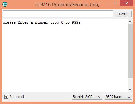
Important code lines are commented in the code. In this code you can send any number from 0 – 9999 through the serial monitor (refer the image given above). We are using the arduino timer interrupts to switch between digits. The segments should be turn on and off for each number is stored in a byte array. In the loop() – serial values are read and converted to int and then to long data types. Then this long data is broke in to single digits by break_number () method. Multiplexing is done by the timer class every() function and it calls display_number() method once every millisecond. This method use arduino shiftOut () function to send signals to shift register. Note how latch pin is turned LOW before we send data and turned HIGH after sending data. The function called cathode_high() is to turn off the screen.
Results
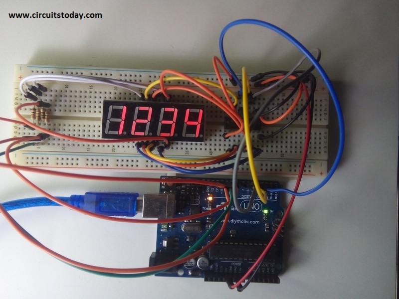
Following image shows the actual setup of the above circuit and the final results!
So that’s how we interface 7 segment display to arduino. And we have learned how to connect single digit 7 segment display and 4 digit seven segment display to arduino with their arduino programs. If you have any doubts, please ask in comments section.
11 Comments
can i use the 2 digit only by the same code?
sir what will be program for multiplexing 7 segment 4 digits without shift resistor.
thankyou for this tutorial… I made one using your tutorial everything is good except the timer is not decreasing. it only displays the number we input, it is not decreasing, please help