Description.
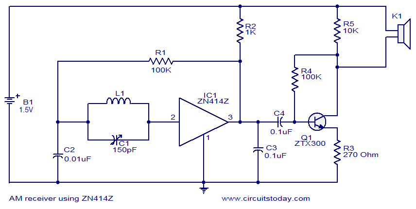
This is the circuit diagram of the simplest single chip AM radio. The circuit is designed around the IC ZN414Z which is a ten transistor tuned radio frequency receiver .The IC has only three leads and is available in the TO92 package. All necessary circuits required for an AM receiver (RF amplifier, detector and AGC are incorporated inside the IC).In the circuit given below, capacitor C1 and resistor R1 forms the tank circuit which is essential for tuning. Capacitor C4 decouples DC from the output of the IC and C1 bye-passes the noise. Transistor Q1 and associated components forms a classic driver stage for the headphone. Head phone is connected across the resistor R5 and R4 gives necessary biasing for the transistor Q1.
Circuit diagram.
Notes.
- Assemble the circuit on a good quality PCB.
- The circuit can be powered from a 1.5V cell.
- Do not give more than 1.8V to the circuit as it will destroy the IC.
- For L1 make 80 turns of 0.3mm enameled copper wire on a 5cm long ferrite rod.
- K1 can be a high impedance crystal earpiece.


20 Comments
pls how do i insert the variable capacitor,and is there an alternative for the inductor and the crystal earpiece? And can i use a 8 ohm,0.4W speaker instead of the earpiece?
Pls Admin, what other connections does one need to make to use this circuit with 8ohms 3W speaker instead of earphone. Thanks.
In your ZN414 Radio Circuit I see no place where the battery is inserted.
Now I see where it is, silly me:-)
can i use this circuit with long range AM transmitter ??
Hi colleague! thanks for sending me diverse circuit for diverse projects.
pls. do you have any rf circuit that can be used to trigger a relay?
Just like in your Am receiver circuit, where you used a speaker as your out put. How do i replace that speaker with a relay so that i can you the circuit for another purpose?
TA7642 where to buy in INDIA ?? call me 090-286-70-425
Estaría muy agradecido de ustedes si me hicieran el grande favor de informarme donde puedo conseguir en Colombia el Circuito Integrado: zn414z, quien lo distribuye, o en donde puedo encontrar esta informaciòn, ya que estoy interezado en este circuito.
De antemano mis agradecimientos
Atentamente, Fernando Parra
fdoparraz@gmail.com
Where can I get: Zn414z IC, in the republic of Colombia.
Thanks in advance to serve as the welcome given to my request.
Sincerely,
Fernando Parra Z.
Hello Again,
I do not know in which part of the world the home constructor is living.
Typing ZN414 radio or MK484 even TA7642 IC One can easily reach a source to buy two of above latter one’s via Google.Visiting my homepage and links list reflected on related pages above will direct You to a reliable eBay source that provides TA7642 at a very very reasonable cost.
Good Luck and Happy Experimenting.
Arman Sabciyan
I want to get the components from your company with the required Fees. Is it possible to supply me the component.
Priyabrata Dash
At now we are not supplying components
Hi,
Further to my explanations of yesterday. I have designed a similar circuit omitting the 270 Ohm Resistor( R3 )
You may visit my homepage for full details and information regarding the circuit.
Regards to All
Arman Sabciyan
Hi,
As already mentioned the receiver covers the AM/Medium Wave and LW Long Wave only.Although some try the Short Waves/SW possibly the 49 meter band.As the IC has a top working frequency of 3 MHz.Tha above or similar circuits will work fine with different number of turns according to the variable capacitor value.The coil can be prepared at home need not be any commercial coil preferably with Litz Wire or 30 SWG enamelled copper wire close wound 55 turns for a 365 pf variable capacitor length of ferrite bar/slab about 10 cms for a shorter bar/slab some turns more such as 60 to 65. The number of turns for a ferrite rod should be approximately the same for the same dimensions.One has to try to find the needed number of turns which is not a difficult task as home construction means experimenting.
For Long Wave the number of turns will be about 250 to 300
on a ferrite rod random wound need not be close wound.
If you happen to have a ferrite antenna coil both for LW and MW you can try the original variable capacitor value mentioned in the diagram.
Hope this helps.
Regards
Arman Sabciyan
is there a different material i could use besides ferrite, because i am having trouble finding a ferrite rod with those measurements.
L1 can be 90turns of 28 to 32 SWG wire on 3/8 inch dia ferrite rod of 6inches in length to cover MW frequencies.
Hi, i am building is circuit for my class, and i’m new to the whole world of circuits, but what kind of inductor should be used for the tank circuit in Henry’s?
thanks
Hi Tanmay it will work nicely on Medium Wave will pick up AM local stations. This IC cannot demodulate FM signals. For FM use SONY 1619 is the best.
hey does this circuit works and do we get to hear fm channels on this?
Hi,
I am mainly interested in ZN414 or the alternatives MK484
or TA 7642 IC radios.
This is a very efficient circuit.Unfortunately there are vere limited number of circuits which are identical and related to this 10 transistor chip.
Maybe according to request more circuits will arrive
by designers.
I am following your webpage with extreme interest.
Link to my personal homepage is reflected below.
Space above was insufficient.
Best Regards
Arman Sabciyan