In electronic ac voltmeters input signal is firstly rectified and then supplied to the dc amplifier, as shown in figure. Sometimes signal is firstly amplified by ac amplifier and then rectified before supplying it to dc meter, as shown in figure. In the former case the advantage is of economical amplifiers and the arrangement is usually used in low priced voltmeters.
Broadly ac voltmeters can be divided into three categories.
1. Average Reading AC Voltmeters.
Normally ac voltmeters are average responding type and the meter is calibrated in terms of the rms values for a sine wave. Since most of the voltage measurements involve sinusoidal waveform so this method of measuring rms value of ac voltages works satisfactorily and is less expensive than true rms responding voltmeters. However, in case of measurement of non-sinusoidal waveform voltage, this meter will give high or low reading depending on the form factor of the waveform of the voltage to be measured.
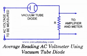
The circuit diagram for an average reading voltmeter using a vacuum tube diode is shown in figure. The arrangement requires a vacuum tube diode, an high resistance (of the order of 105 Q.) R and PMMC instrument, all connected in series, as shown in fig. Resistance R is used to limit the current and make the plate
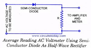
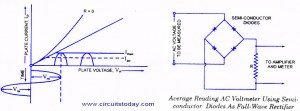
voltage-current characteristics linear. The linear plate characteristics are essential in order to make the current directly proportional to voltage. Also because of high series resistance R, plate resistance of vacuum tube diode becomes negligible and therefore variations in plate resistance do not cause non-linearity in voltage-current characteristics. In this way we get the scale of PMMC instrument uniform and independent of variations of tube plate resistance. Voltage across the high resistance is fed to dc amplifier and output of the amplifier is fed to PMMC instrument. Circuit diagram of an average reading ac voltmeter using semi-conductor diode is shown in figure. The diode conducts during the positive half cycle and does not conduct during the -ve half cycle, as shown in figure.
The average current through the meter will be given by the expression
Iav = Vav / 2R = 0.45 * [Vrms/R]
Vrms is the effective or rms value of applied voltage and 1.11 is the form factor of sinusoidal wave. R is multiplied by 2 because the voltmeter operates on half-wave rectification. It is to be worthnoting that this instrument can be used to indicate dc voltages but in such a case the instrument readings will have to be multiplied by 2 x 1.11, that is, as the diode conducts all the time. Circuit diagram of an average reading ac voltmeter using semi-conductor diodes as a full-wave rectifier is shown in figure. In this case average current through the meter will be Vrms/ 1.11R. Main advantages associated with these voltmeters are that they are simple in construction, have high input impedance, low power consumption and uniform scale. Main disadvantage of these voltmeters is that these operate in audio-frequency range. In radio-frequency range, distributed capacitance of the high resistance R introduces error in the readings.
Another disadvantage of such a voltmeter is that due to non-linear volt-ampere characteristic for lower voltage the readings of the voltmeter at lower voltage are not correct.
2. Peak Reading AC Voltmeters.
The circuit diagrams for peak reading voltmeter using vacuum tube and semi-conductor diode are shown in figures respectively.
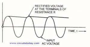
In this type of voltmeters capacitor C is charged to the peak value of .the applied voltage and capacitor -is discharged through the high resistance R between two peaks of the wave which results in a small fall in capacitor voltage. But this voltage is again built up during next peak of the wave, as shown in figure. So voltage across capacitor C and resistance R remains almost constant and equal to the peak value of the applied voltage.
Either the average voltage across R or the average current through R, can be used to indicate the peak value of applied voltage. In case the vacuum tube diode (or semi-conductor diode), series resistance R shunted by capacitance C and PMMC are connected in series across the source of unknown voltage, the current through the PMMC will indicate the peak value of applied voltage.
In case, the circuit shown in figure making use of rectifying diode, series resistance R, dc amplifier and PMMC is employed, the average voltage across R will indicate the peak value of applied voltage. This alternative is preferred, as explained earlier, the power consumption can be reduced by making series resistance R high. By making series resistance R high a less sensitive type of PMMC instrument can also be used. The high value input resistance also gives more linear relationship between peak applied voltage and the instrument indication. Also the performance of the diode with inputs consisting of pulses and modulated waves is improved.
The dc amplifier associated with the diode rectifier should be provided with stabilizing means in order to prevent drift in the indication of the output meter. Usually a voltage regulated supply combined with a compensating circuit is used.
The use of high series resistance R, associated with dc amplifier, no doubt results in a high input resistance but at the same time it implies that an applied voltage of sufficient amplitude is required so that the system acts as a peak voltage device. The main disadvantage of this system is with regards to measurement of low voltage. If the applied voltage is too small, then there is a flow of some current throughout the cycle of the voltage because of high velocity of emission of electrons, and the input resistance may be a few hundred ohms and it defeats the very purpose with which electronic instruments are used.


8 Comments
I think there is some information missing here. First there are two different readings for the voltage beween pins 3 & 4. Eithe this is an error or outside conditions have changed. If I assume the simple circuit of a diode and a resistor is used, The readings across pins 10 &8 and across pins 1 and 8 indicate the presence of both DC and AC, 0.5 V DC and an ac wqaveform with an average value of ~28V – 0.5V + Vd, where Vd is the forward drop of the diode. However, the first reading across pins 3 and 4 is not possible unless the AC voltmeter is capacitively coupled.
Ted Stone. WA2WQN
Using a voltmeter to take different readings. One set of readings was taken on an AC scale setting and then another on a DC scale setting. Because I was able to read AC, wouldn’t this circuit be an AC circuit, not a DC circuit? If this were a DC circuit, I wouldn’t be able to get a voltage reading on the AC scale setting…….or would I.
Across Pins #10 and #8 – 28.7 VAC / .5 VDC
Across Pins #3 and #4 – 14.1 VAC / 17.2 VDC
Across Pins #1 and #8 – 28.1 VAC / .5 VDC
Across Pins #3 and #4 – 0 VAC / 16.6 VDC