In this article, we focus on Timers/Counters of the 8051 micro controller. The 8051 has two counters/timers which can be used either as timer to generate a time delay or as counter to count events happening outside the microcontroller.
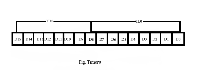
The 8051 has two timers: timer0 and timer1. They can be used either as timers or as counters. Both timers are 16 bits wide. Since the 8051 has an 8-bit architecture, each 16-bit is accessed as two separate registers of low byte and high byte. First we shall discuss about Timer0 registers.
Timer0 registers is a 16 bits register and accessed as low byte and high byte. The low byte is referred as a TL0 and the high byte is referred as TH0. These registers can be accessed like any other registers.
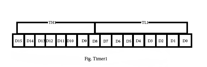
Timer1 registers is also a 16 bits register and is split into two bytes, referred to as TL1 and TH1.
TMOD (timer mode) Register: This is an 8-bit register which is used by both timers 0 and 1 to set the various timer modes. In this TMOD register, lower 4 bits are set aside for timer0 and the upper 4 bits are set aside for timer1. In each case, the lower 2 bits are used to set the timer mode and upper 2 bits to specify the operation.
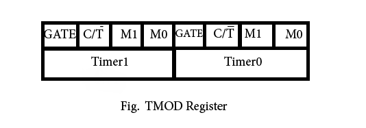
In upper or lower 4 bits, first bit is a GATE bit. Every timer has a means of starting and stopping. Some timers do this by software, some by hardware, and some have both software and hardware controls. The hardware way of starting and stopping the timer by an external source is achieved by making GATE=1 in the TMOD register. And if we change to GATE=0 then we do no need external hardware to start and stop the timers.
The second bit is C/T bit and is used to decide whether a timer is used as a time delay generator or an event counter. If this bit is 0 then it is used as a timer and if it is 1 then it is used as a counter.
In upper or lower 4 bits, the last bits third and fourth are known as M1 and M0 respectively. These are used to select the timer mode.
M0 M1 Mode Operating Mode
0 0 0 13-bit timer mode, 8-bit timer/counter THx and TLx as 5-bit prescalar.
0 1 1 16-bit timer mode, 16-bit timer/counters THx and TLx are cascaded; There are no prescalar.
1 0 2 8-bit auto reload mode, 8-bit auto reload timer/counter; THx holds a value which is to be reloaded into TLx each time it overflows.
1 1 3 Spilt timer mode.
Mode 1- It is a 16-bit timer; therefore it allows values from 0000 to FFFFH to be loaded into the timer’s registers TL and TH. After TH and TL are loaded with a 16-bit initial value, the timer must be started. We can do it by “SETB TR0” for timer 0 and “SETB TR1” for timer 1. After the timer is started. It starts count up until it reaches its limit of FFFFH. When it rolls over from FFFF to 0000H, it sets high a flag bit called TF (timer flag). This timer flag can be monitored. When this timer flag is raised, one option would be stop the timer with the instructions “CLR TR0“ or CLR TR1 for timer 0 and timer 1 respectively. Again, it must be noted that each timer flag TF0 for timer 0 and TF1 for timer1. After the timer reaches its limit and rolls over, in order to repeat the process the registers TH and TL must be reloaded with the original value and TF must be reset to 0.
Mode0- Mode 0 is exactly same like mode 1 except that it is a 13-bit timer instead of 16-bit. The 13-bit counter can hold values between 0000 to 1FFFH in TH-TL. Therefore, when the timer reaches its maximum of 1FFH, it rolls over to 0000, and TF is raised.
Mode 2- It is an 8 bit timer that allows only values of 00 to FFH to be loaded into the timer’s register TH. After TH is loaded with 8 bit value, the 8051 gives a copy of it to TL. Then the timer must be started. It is done by the instruction “SETB TR0” for timer 0 and “SETB TR1” for timer1. This is like mode 1. After timer is started, it starts to count up by incrementing the TL register. It counts up until it reaches its limit of FFH. When it rolls over from FFH to 00. It sets high the TF (timer flag). If we are using timer 0, TF0 goes high; if using TF1 then TF1 is raised. When Tl register rolls from FFH to 00 and TF is set to 1, TL is reloaded automatically with the original value kept by the TH register. To repeat the process, we must simply clear TF and let it go without any need by the programmer to reload the original value. This makes mode 2 auto reload, in contrast in mode 1 in which programmer has to reload TH and TL.
Mode3- Mode 3 is also known as a split timer mode. Timer 0 and 1 may be programmed to be in mode 0, 1 and 2 independently of similar mode for other timer. This is not true for mode 3; timers do not operate independently if mode 3 is chosen for timer 0. Placing timer 1 in mode 3 causes it to stop counting; the control bit TR1 and the timer 1 flag TF1 are then used by timer0.
TCON register- Bits and symbol and functions of every bits of TCON are as follows:
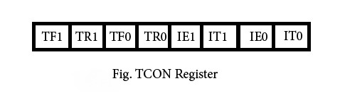
BIT Symbol Functions
7 TF1 Timer1 over flow flag. Set when timer rolls from all 1s to 0. Cleared
When the processor vectors to execute interrupt service routine
Located at program address 001Bh.
6 TR1 Timer 1 run control bit. Set to 1 by programmer to enable timer to
count; Cleared to 0 by program to halt timer.
5 TF0 Timer 0 over flow flag. Same as TF1.
4 TR0 Timer 0 run control bit. Same as TR1.
3 IE1 External interrupt 1 Edge flag. Not related to timer operations.
2 IT1 External interrupt1 signal type control bit. Set to 1 by program to
Enable external interrupt 1 to be triggered by a falling edge signal. Set
To 0 by program to enable a low level signal on external interrupt1 to
generate an interrupt.
1 IE0 External interrupt 0 Edge flag. Not related to timer operations.
0 IT0 External interrupt 0 signal type control bit. Same as IT0.
5 Comments
@Abdul – Please subscribe to our email newsletter.
A very nice article in suitable language not only for knowledge full person
but also for beginner.The writer is surely having good and deep knowledge its reflects in the contents of the article. AWESOME! waiting for next article .
THANKS A LOT
thank you sir