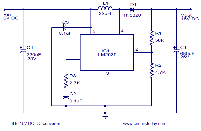
6 to 15V DC to DC converter using LM2585
Description.
A very efficient 6V to 15V DC to DC converter using LM2585 is shown here. LM2585 is a monolithic integrated voltage converter IC that can be used in various applications like flyback converters, boost converters, forward converters, multiple output converters etc. The circuit requires minimum number of external components and the IC can source up to 3A output current.
Here the IC is wired as a boost converter where resistors R1 and R2 are used to set the output voltage .The junction of R1 and R2 is connected to the feedback pin of IC1. Capacitor C4 is the input filter while capacitor C1 the filter for output. Network comprising of resistor R1 and capacitor C2 is meant for frequency compensation. Inductor L1 stores the energy for acquiring boost conversion.
Circuit diagram of LM2585 DC to DC converter.

- Assemble the circuit on a good quality PCB.
- LM2585 requires a heatsink.
- Output voltage is according to the equation Vout =( (R1/R2)+1) x 1.23.
- Capacitors other than C4 and C1 are ceramic capacitors.
- Maximum output current LM2585 can source is 3A.

21 Comments
is that possible if i will change the ic lm2585 to lm2588 to have a 5A?
Hi,admin
Is the value of L1 critical, if it’s not what’s the tolerance for it to make the circuit still working?…..thank’s
Hi Hasan these inductors are vailable in indian marker freely. costing around Rs10/- per piece on retails if you want to wind use the following formula
L (uH) = (d^2 x n^2)/(18 x d + 40 x l)
where L is in microhenries (uH)
d is the coil diameter in inches from wire center to wire center
l is the coil length in inches
n is the number of turns.
admin please can you tell me about L1? how many turn of coil do i use?
hey guys.
I need some help.
If u can, write to my e.mail,
many thanks.
Thats ground.. I need to connect -6v? In out i have -15v? (ground)
and lm2585, legs location 3 top ant 2 bottom, or 5 in a row?
my email. Jonukasjonas0071@gmail.com
A printing error from my part. its 2.7K
Yes Manish small error it should be 2.7K resistance.
dear sir,
Wat s the value f R3? Is it 2.7k?
Hi I Do yhank all U people extending that knowledge to educte us.How can I send my pieces of wark to U people so as people also get to see ma wark? thanx
Hi CJS Mack seethasub@hotmail.com is my email ID.
facebook.com/cjsmack .thanks
hi seetharaman, thanks for replying can i get ur email add or u cn add me on faceboo.com/cjsmack .thanks
Hi CJS Mack All reference voltage points are called, common and it is indicated as earth with single line. This reference point can be connected to ground for stray noise reduction.
Where ever positive and negative voltages are required like analog circuits Zero volt which is the reference for indicating positive and negative voltages, is taken as common and ground. Where ever ground is shown in the circuit they are connected together. To avoid too many connection and making the circuit simple with clarity i8t is shown this way and it is a standard way of presenting.
i did mistake in my typing at above comment ,here is d correct 1. @ rakeshbute , i now understand you that i should connect d ground 2 d negative in circuits lik the above one , but wot of a circuit lik amplifier that d positive and negative terminals were clearly given on d diagram then , there are lots of ground(earth) shown on the circuit. Pls my question is where to connect those ground ? , is it at the negative too? , God bless u
now understand is wot i mean pls
@ rakeshbute , i knw understand u dat i shud connect d ground 2 d positive in circuits lik d above , but of a circuit lik amplifier that d positive and negative terminals were clearly given on d diagram then , there are lots of ground(earth) shown on the circuit. Pls my question is where to connect those ground ? , is it at the negative too? , God bless u
@CJ smack.
Just follow what vysakh said. If any circuit diagram comes with only a positive supply and one ground. Simply connect the ground to the negetive supply ur using. U will face this in many circuits. actually in software simulated circuits, the node numbering starts from the ground, it is assumed node 0. so u gotta face it.
so in the above circuit , which one is the earth , i need to understand this thing , pls guys help me , and is it only the positive terminal of d 6v circuit , that wil be used on d circuit above , wil d negative b kept constant?
in normal cases, battery -ve terminal(bridge rectifier -ve) considered as earth.but in the dual power supply’s,it vary
admin , pls where is d earth located in amplifier or battery charger , is it @ diode bridge or where please sir