Description.
NE555 is an IC which is widely used in timers and control circuits. A circuit for independent testing this IC is given here.
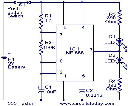
Here the NE555 is wired as an astable multivibrator. When the push button switch S1 is pressed the LEDs D1 & D2 will flash alternatively. That is when output is high D2 will glow & when output is low D3 will glow. The rate of flashing will depend on components R1,R2 & C1.
When push button S1 is pressed,C1 will start charging through R1&R2.When the voltage across C1 rises above 2 of 3 is the supply voltage the internal Flip Flop toggles . The pin 7 becomes low & C1 starts discharging. When the voltage across C1 goes below 1of 3 of supply voltage the internal Flip Flop resets & pin7 goes high. The C1 again starts charging.All this will take place if the IC is healthy.
According to the frequency of this charging & discharging D1&D2 will flash. From these observations we can conclude that IC NE555 is faulty or not .
Circuit diagram with Parts list.
Notes.
- Assemble the circuit on a good quality PCB or common board.
- Power the circuit from a 9V radio battery.
- If D1 and D2 flashes on the pressing of S1,we can assume that the IC is working.
3 Comments
hi setharam ,manish is right the leds are not lighting alternatively
i had connected a electrolytic cap for the value 10uF and ceramic cap for 0.001uF,nd then,the first LED blinks nd second bulb glows continuously…pls help.I think 0.001uF cap is not working for ckt…
Thanks alot sir .