TX-2B / RX / 2B 5 channel radio remote control.
This article is about a simple 5 channel radio remote control circuit based on ICs TX-2B and RX-2B from Silan Semiconductors. TX-2B / RX-2B is a remote encoder decoder pair that can be used for remote control applications. TX-2B / RX-2B has five channels, wide operating voltage range (from 1.5V to 5V), low stand by current (around 10uA), low operating current (2mA), auto power off function and requires few external components. The TX-2B / RX-2B was originally designed for remote toy car applications, but they can be used for any kind of remote switching application.
Circuit diagrams and description.
Remote encoder / transmitter circuit.

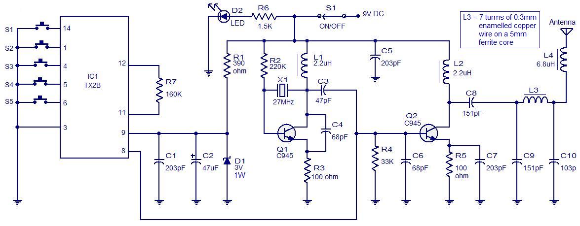
The TX-2B forms the main part of the circuit. Push button switches S1 to S5 are used for activating (ON/OFF) the corresponding O/P channels in the receiver / decoder circuit. These push button switches are interfaced to the built-in latch circuitry of the TX-2B. Resistor R7 sets the frequency of the TX-2B’s internal oscillator. Resistor R1 and Zener diode D1 forms a simple Zener regulator circuit for providing the IC with 3V from the 9V main supply. C2 is the filter capacitor while C1 is a noise by-pass capacitor. D2 is the power on indicator LED while R6 limits the current through the same LED. S1 is the ON/OFF switch. The encoded control signal will be available at pin 8 of the IC. The encoded signal available at pin 8 is without carrier frequency. This signal is fed to the next stage of the circuit which is a radio transmitter. Crystal X1 sets the oscillator frequency of the transmitter section. R2 is the biasing resistor for Q1 while R3 limits the collector current of Q1. The encoded signal is coupled to the collector of Q1 through C3 for modulation. Transistor Q2 and associated components provide further amplification to the modulated signal.
Remote receiver / decoder circuit.

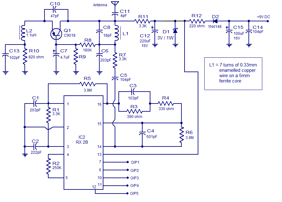
The remote receiver circuit is built around the IC RX-2B. The first part of the circuit is a radio receiver built around transistor Q1. The received signal is demodulated and fed to pin 14 of the IC. Pin 14 is the input of the built in inverter inside the IC. R2 sets the frequency of the IC’s internal oscillator. O/P 1 to O/5 are the output pins that are activated corresponding to the push buttons S1 to S5. Zener diode D1 and resistor R12 forms an elementary Zener regulator for supplying the RX-2B with 3V from the 9V main supply. C12 is the filter capacitor while R11 is the current limiter for the radio receiver section. Diode D2 protects the circuit from accidental polarity reversals. C15 is another filter capacitor and C14 is a noise by-pass capacitor.
Notes.
- This circuit can be assembled on a vero board or a PCB.
- Use 9V DC for powering the transmitter / receiver circuits.
- Battery is the better option for powering the transmitter / receiver circuit.
- If you are using a DC power supply circuit, it must be well regulated and free from any sort of noise.
- Both ICs must be mounted on holders.
Interfacing relay to the RX-2B output.
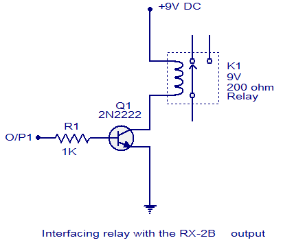
The method for interfacing a relay to the output of RX-2B is shown below. When push button switch S1 of the transmitter circuit is pressed, pin O/P1 (pin 7 of the RX-2B) goes high. This makes the transistor 2N2222 to conduct and the relay is activated. The same technique can be applied to other output pins of the RX-2B. The relay used here is a 200 ohm type and at 9V supply voltage the load current will be 45mA which is fine for 2N2222 whose maximum possible collector current is 900mA. When using relays of other ratings this point has to be remembered and do not use a relay that consumes a current more than the maximum possible collector current of the driver transistor.


98 Comments
Hi. Thanks for the tutorial.
What do I need to change on the receiver to change from 27Mhz to another frequency?
Thank you.
Hi and thanks for this useful website..
i’m an RC lover? specially for TX-2B/RX-2B.. and i’m looking for an electronic software simulator that contains that chips on its librairies to simulate signals, frequency,…
if someone can help me for that it will be great for me.
thank you .
One more quick question, what size antenna should i use for the remote control?
5-channel-radio-remote-control
Can anyone please tell me what are the actual size of the capacitors in the decoder? I cannot find any capacitor with the value 501 pF and 4 pF
5-channel-radio-remote-control
Where I connect the dc motor????
Connect it to the relay
Am a beginner dnt knw were to purchase my electric component i.e transmitter,recievers and servo motors and i dnt have credit card to shop in hobbyking can i buy it in nigeria here and can they bring it to my door step
please all the component listed here how can i get it in Nigeria or how would i ship it give me some links through my email please
hi how can i connect the o/p to servo motors please i am a beginner
google search “H-bridge”
And what will be its range (in metre)?
Here in transmitter and receiver circuits, what does ground(GND) actually means to be? the negative terminal or the earthing?
Please help me sir to understand it.
Thanks……In advance.
Can you see there is none connected 13 terminals in encoder/transmitter circuit.
those are the Grounds. You must connect all of these together and finally to the negative of the battery.
It means the negative terminal. On schematics, a ground symbol
is used instead of drawing lines to connect components to the
negative terminal of an electrical voltage source.
hello seetharaman sir….
all 5 channel works simultaneously or not??
at a time only one channel can carry the signal???
or at a time all channels can carry the on/off signal???
if at a time all channel carries the signal
then can I fed different different PWM to input of transmitter simultaneously??
and can I get different different PWM on corresponding channels at receiver simultaneously ??
Only one channel at a time will work. Its range is also limited to inside a room only.
sir… can you provide the 5 channel or more channel RC controller circuit
where all channels can works simultaneously
and all channels can carry the signal like PWM and not only ON/OFF signal.
as well as range should be wide…..
please reply
what is it’s range??
Five meters, but you could extend the range using power amplifier.
Sir please can i use this circuit for my aircraft? If yes then how. Thank you.
No this cannot be used as there is no analog output, no proportional control activity can be carried out, only binary output is available with this remote.
Do you know any circuit can carry analog signal for proportional control, such as controlling servo motors. If so could you share diagram of circuit and chips required with us ? thanks
Pls help me….output of rx2b is analog or digital???
It is on/off digital output. 5 channel indicates five independent binary output to control 5 independent on/off functions.
The output is either zero volts or a positive voltage, such as 5 volts.
The 5 volts will turn on a transistor relay driver.
Hi Seetharamen, i built the circuit of RX in my protoboard. But i realized that the 1N4148 doesn’t have any voltage, and the rest of the circuit also doesn’t have.
Now, do you know if the 1N4148 have the function of open and close the circuit?
The chip RX-2B only will run when Tx-2b run togheter?
what is 5 channel means
I guess 5 inputs and 5 outputs
hello
may specify the full part number of IC1 and IC2 please?
thanks in advance
what is the value of tx 2b and rx 2b i don’t know the value
Hi Sir,
Are we use “O/P” signal on the L293D ınput leg? Thank you in advance.
Are we use “O/P” signal on the L293D ınput leg? Thank you in advance.
Hi
I built the circuit of TX in a printed circuit board, and now, I need to build the RX
My doubt is how I crank the engine that my car with the circuit of RX?
We have two engines to crank. How I make it?
If you want to crank two together use one output with a relay’s two NO (normally open contacts) contacts.
Hi Seetharaman, just so u know i had another question on that 2km transmitter posted since last friday.
OK, but i wouldn’t rather use relay.
I saw on the datasheet of Silan, this circuit have been actived by transistor. Can I use these? Please, help me!
You have a kit , how many ruees
1) Sir you said it’s 5 channel remote control but how can i connect the motors? 2) and how can i control the motors? 3) and sir the value of R9 is missing. Thank you.
It is just with high low output only you have to use proper interfaces to drive motor on/off forward/ reverse etc. analog control of speed is not possible (slow fast etc). R9 is 100 K ohms 1/4 watt see earlier detailed comments.
where is C9 for the receiver
the R9 value is now mentioned there could u pls give the reason or tell something to find it out with some sort of method or pls give the value of that resistor
I want try it. but, how built part of coil L2, L3, L4 both side RX and TX? Then, what name of IC’s type?
I want try its…
hi im entirely new to electronics so i have lot of doubts about the circuit and here they are
1) you said its 5 channel but the circuits shows only two motor connection
2) how can i control 5 motors using this circuit
pls clarify my queries
1 turbo
2 forward
3 reverse
4 left
5 right
i want try it, but how i can get all componen from thats circuit. i need it.
Can i use this for 100m distance.i’m beginers to radio control.what is the ic number of TX-2B &RX-2B
Range is 5 meters, however there are power amplifier circuits that
can extend the range.
This is a nice circuit and thanks for sharing. however, value of R9 is missing. could you please let us know it.
what is the value of R2 Rx for 315mhz R7 Tx for a frequency of 315mhz
Operation frequency of TX2B and RX2B IC is within 100 to 150KHz only. Please manufacturers data sheet
what is the range for the transmitter and receiver in this circuit? and value of R9?
very interesting and educational controls
thanks very much .
ashok gajjar .
IF any one has a good experience of this circuit, and please tel us that, how for could this remote works?
if i can attach big antenna, can i use this for @ least 100 meters?
thanx if any one can answer.
sir please give the value of R9
thank you
Hi Xavier please go through earlier comment before raising a question. please see my comment of 15th july 2013.
i want suppliers in india ic rx2b and tx 2b
sir ..plz tell me…. both IC was not found in my city market …plz help me to related IC ……& what is the cost of IC-RX 2B, TX 2B……..PLZ
they are available ebay, with free shipping. I just ordered a pair of tx2b and rx2b, just for 2.45 usd.
sir give me your EMAIL ID gmail/facebook ……. I AM WATING
MY FACEBOOK USERNAME rock1223
seethasub@hotmail.com
thanx sir
SIR
Seetharaman THANX THANX THANX
A LOTE OF THANX
sir plz tell me R9 & the given capicter is cap. value or cap. no plz reply me hear or in ID -avinashkumar20rock@gmail.com PLZ PLZ PLZ
wht is the valu of R9 PLZ TEL ME
My ID is here-
avinashkumar20rock@gmail.com
Hi Avinash R9 should be 100 Kohms
i want similer ic of TX-2B & RX-2B this 2 ic not goted in market.
is this circuit tested
Has any one tried this circuit practically
Did this work?
iam trying now and no result and iam disappointed
yes i tried and success
how can i get latch output from RX2B directly???
if i can’t get latch output directly which method can i get latch output??????
help me please
pls how the safty of that circuit ? can it work from another transmitter of by a random signal?
what is the operating frequency of that transmitter and receiver ?
nice , great work
what is the value of resistor R9 ???????????
TX-2B / RX / 2B 5 channel radio remote control
what is the value of resistor R9…?
what is R9 AND R8 in receiver circuit
what is the operating frequency of that transmitter and receiver and what is the maximum distance they can handle ?
this rc circuit is where intrested for making but the problems ic where should i get this ic in bhayander electronic shop call me at9322746975 call at 1: 30 am till tonigt of 8:00 pm
Where i can ordered??
i want get 5channel radio remote control
wow………..it’s very much intresting and easy
Wonderful Explanation and Circuit
but give Little Idea regarding Antenna…..
Can we transmit any audio signal using these ic s
http://www.elenota.pl/datasheet-pdf/135839/Silan-Microelectronics/TX2B
Above is the website datasheet of the 5-function remote controller RX-2B and TX-2B.I have an important question: In the typical application RF Circuit transmitter and receiver, they show a High pass filter CAPACITOR in the receiver that connect to pin 3(SI)which is the input pin of the encoding signal of RX-2B and a RESISTOR with a zener diode. I would like to know what is the value of the CAPACITOR and the RESISTOR in the receiver?
Thank you.
can u please tell me the value of coil l 3 in “5 channel radio remote control ” in henry ….
hello,
concerning the “5 channel radio remote control”:
– what can be the maximum possible distance between transmitter and reciever?
– are these circuits already assembled and where to buy?
thanks for your very interesting contribution.
best regards
D. Lambelet
i found this IC in a remote control car.the brand of the toy is TOPSPEED.
to interface other circuit to it you must use relay.
will u pls give me the ic number forreciever and transmitter circuit. specifyas many alternative ic number aspossible for both the circuits.
will u pls give me the ic number for reciever and transmitter circuit. specify as many alternative ic number as possible for both the circuits.
can u give me a number of the ic
thanks
heide
is it necessary to connect interfacing relay circuit to the rx-2b or it will do with out it.
its urgent please reply me as fast as possible.
plz….
please reply me
i need 10 channel RF remote for my new project. Can i adopt this circuit
hy this ic rx 2b doesn t have so much outs it have only 5.if you want 10 channels i suggest you to build 2 transmitters and 2 receivers using 2 different cristals !!! 27 and 40 mhz for instance