Voltage Converter Circuit.
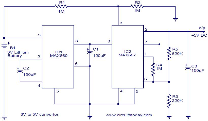
Circuit given below is a 3V to 5V Voltage converter using CMOS IC MAX660 and MAX667.
Description :
In the circuit shown below, a 3V to 5V converter is implemented using MAX660 and MAX667. MAX660 is a CMOS monolithic voltage converter and MAX667 is a programmable low dropout positive voltage regulator. Here MAX660 performs the job of voltage boosting and MAX667 regulates the output of MAX660 inorder to give a steady 5V DC output.
Circuit diagram of 3v to 5v converter:
Notes about voltage converter circuit:
- The circuit can be assembled on a vero board.
- IC1 and C2 must be mounted on holders.
- Load current must not exceed 200mA.
You may be interested in more Volatge converter circuits in our website:
3. Voltage Doubler and Inverter
4. 12V Boost Regulator Circuit
5. Positive to Negetive Voltage Converter
If you are interested in more Power supply related circuits, please check our category on Power Supply Circuits


1 Comment
MAX660 &MAX667 IC ARE NOT AVAILABLE