Description.
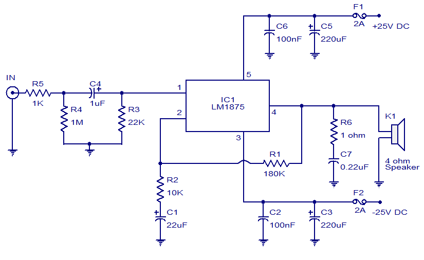
This is just another 20W audio amplifier circuit , but this time based on the LM1875 audio amplifier IC from National Semiconductors. With a 25V dual power supply LM1875 can deliver 20W of audio power into a 4 ohm speaker. The LM1875 requires very less external components and has very low distortion. The IC is also packed with a lot good features like fast slew rate, wide supply voltage range, high output current, high output voltage swing, thermal protection etc. The IC is available in TO-220 plastic power package and is well suitable for a variety of applications like audio systems, servo amplifiers, home theatre systems etc.
Circuit diagram.
Notes.
- Assemble the circuit on a good quality PCB.
- Use +/-25V DC dual supply for powering the circuit.
- K1 can be 4 ohm, 20W speaker.
- A proper heat sink is necessary for the IC.
- F1 and F2 are 2A fuses.


7 Comments
hi.. i am a beginner in this, can anyone tell me what to do with that grounds shown in the figure?
where should it be connected
is LM4753 2x10W or 2x5W
I want to design “MICROPHONE PRE-AMP 2stage 12V”
Anyone with cercuit diagram plz.
Hi this is an aplication circuit by national semiconductor. not a patented circuit can be reproduced
hi,
Circuit today is the most efficient and the best site for all aspiring electronics engineers and professional engineers.
You are number one.
Hi Emmi you can use the subwoofer filter appeared in these column earlier as “Car subwoofer filter”
as .1 and the left and right channel signal as 2. then this combination will become 2.1 use a minimum 40watts RMS amplifier for sub woofer and around 8 watts RMS for Left and right channel front speakers. ( the stereo image is from mid and high frequencies not from low notes which are felt not listened.)
i want circuit diagram for 2.1 channel (not 2.0) i.e one for sub-woofer and two for speaker