Description.
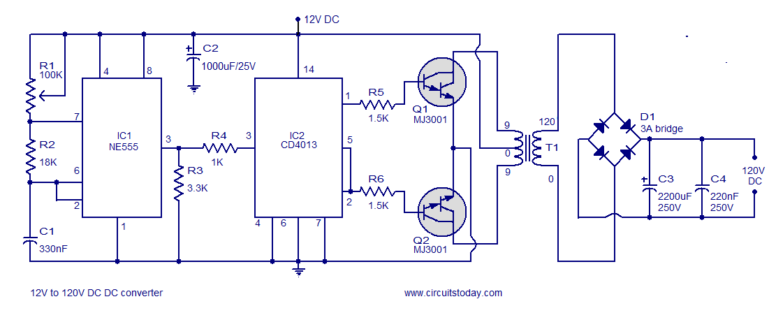
A simple 12V to 120V DC DC converter circuit is shown here. The circuit consists of two stages firstly a basic inverter stage and then a rectifier plus filter stage. IC1 NE555 is wired as an astable multivibrator operating at a frequency of 100Hz and it can be adjusted using the preset R1. Output of IC1 is coupled to the clock input of IC2 which is a CMOS dual D Flip-Flop. IC2 divides the 100Hz pulse train from IC1 into two 50Hz pulse trains which are 180 degree out of phase and are available at pin 1 and 2 of the IC2. When pin 1 is high transistor Q1 conducts and current flows through the upper half of T1s primary winding. When pin 2 is high transistor Q2 conducts and current flows through the lower half of the T1s primary winding. As a result a 120V AC voltage will be induced in the secondary of T1. This voltage is rectified using bridge D1 to produce 120V DC output. Capacitor C2 is the input DC filter while C3, C4 are output filters.
Circuit diagram.
Notes.
- The circuit can be assembled on a vero board.
- Q1 and Q2 require heat sink.
- Output power of this dc dc converter is around 100 watts.
- IC1 and IC2 are to be mounted on holders.
- An optional 5A fuse can be added in series to the 12V supply line.
- T1 can be a 9-0-9V /250V/3A mains transformer.
- If 3A bridge is not available make one using 1N5408 diodes.
- Out of the two Flip-Flops inside CD4013 only one is used here.
- Output of IC1 must be set to 100Hz by adjusting preset R1


13 Comments
Help me, how can I design DC/DC converter 5v USB to 120v output?
Thank you
Help me, how can I design DC/DC converter 5v to 120v output
It is a good and simple circuit. Is it possible to have STEP UP TRANSFORMER details.
How to build “12V to 500V 1mA DC DC converter”.
Thanks!
help me when i start this project
thank you
this is one type of inverter or something else please guide me
Hi cjsmack, in above circuit you can give earthing directly to the Negative(-ve) of the supply voltage (source). Here you should remember that your earthing shuld be perfect otherwise keep one discharge wattage resistor between -ve and your earth.
@ admin , y dont u help me
SEETHARAMAN pls i need ur help bro , cn u send me ur email add or are you on 2go(an application for chatting) ,cjsmack is my user name on 2go . Thank u
In the notes T1 should be 9-0-9 / 120Volt 1Amp
pls admin im confused at some thing, wher can i locate th ‘earth’ in all d circuit you have here , lik amplifiers ,battery chargers, simple ups , pls i wil lik 2 knw d earth location in these circuits , im a beginner SIR